


Before each closing detection, the circuit breaker must be recognized as being open for the settable time 1133
T DELAY SOTF
.
Address 1135
Reset Trip CMD
determines under which conditions a trip command is reset. If
CurrentO-
penPole
is set, the trip command is reset as soon as the current disappears. It is important that the value set
in address 1130
PoleOpenCurrent
(see above) is undershot. If
Current AND 52a
is set, the circuit-
breaker auxiliary contact must send a message that the circuit breaker is open. It is a prerequisite for this
setting that the position of the auxiliary contacts is allocated via a binary input.
For special applications, in which the device trip command does not always lead to a complete cutoff of the
current, the setting
Pickup Reset
can be chosen. In this case, the trip command is reset as soon as the
pickup of the tripping protection function drops off and - just as with the other setting options- the minimum
trip command duration (address 240) has elapsed. The setting
Pickup Reset
makes sense, for instance,
during the test of the protection equipment, when the system-side load current cannot be cut off and the test
current is injected in parallel to the load current.
While the time
SI Time all Cl.
(address 1132, see above) is activated following each recognition of line
energization,
SI Time Man.Cl
(address 1150) defines the time following manual closure during which
special influence on the protection functions is activated. This parameter can only be set in DIGSI at Display
Additional Settings.
i
i
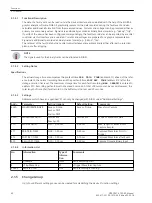
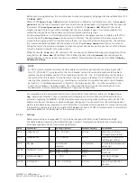
NOTE
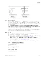
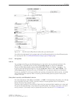
For CB Test and automatic reclosure the CB auxiliary contact status derived with the binary inputs >CB1 ...
No. 371, 410 and 411) are relevant for the circuit-breaker test and for automatic reclosure to be able to
indicate the circuit-breaker position. The other binary inputs >CB ... (no. 379 and 380) are used to detect
the status of the line (address 1134) and to reset the trip command (address 1135). Address 1135 is also
used by other protection functions, e.g. switching on overcurrent. For applications with 2 circuit breakers
per feeder (1.5 circuitbreaker systems or ring bus), the binary inputs >CB1... must be connected to the
correct circuit breaker. The binary inputs >CB... then need the correct signals for detecting the circuit-
breaker status. In certain cases, an additional CFC logic may be necessary.
For commands via the integrated control (local control, DIGSI, serial interface) address 1152
Man.Clos.
Imp.
determines whether a close command via the integrated control function should be treated by the
protection regarding the MANUAL CLOSE (like instantaneous re-opening when switching onto a fault). This
address also informs the device to which switchgear this applies. You can select from the switching devices
which are available to the integrated control. Select the circuit breaker which operates for manual closure and,
if required, for automatic reclosure (usually Q0). If none is set here, a CLOSE command via the control will not
generate a MANUAL CLOSE impulse for the protection function.
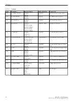
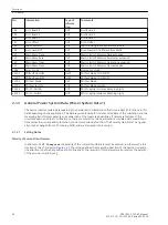
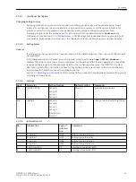
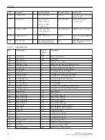
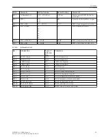
Settings
Addresses which have an appended “A” can only be changed with DIGSI, under “Additional Settings”.
The table indicates region-specific default settings. Column C (configuration) indicates the corresponding
secondary nominal current of the current transformer.
Addr.
Parameter
C
Setting Options
Default Setting
Comments
1103
FullScaleVolt.
0.4 .. 500.0 kV
10.0 kV
Measurem:FullScale-
Voltage(Equipm.rating)
1104
FullScaleCurr.
10 .. 20000 A
400 A
Measurem:FullScaleCur-
rent(Equipm.rating)
1107
P,Q sign
not reversed
reversed
not reversed
P,Q operational measured
values sign
1130A
PoleOpenCurrent
1A
0.05 .. 1.00 A
0.10 A
Pole Open Current
Threshold
5A
0.25 .. 5.00 A
0.50 A
1131A
PoleOpenVoltage
2 .. 70 V
30 V
Pole Open Voltage
Threshold
1132A
SI Time all Cl.
0.01 .. 30.00 sec
0.10 sec
Seal-in Time after ALL
closures
2.1.6.2
Functions
2.1 General
SIPROTEC 4, 7SD80, Manual
43
E50417-G1100-C474-A2, Edition 02.2018
Summary of Contents for SIPROTEC 4 7SD80
Page 8: ...8 SIPROTEC 4 7SD80 Manual E50417 G1100 C474 A2 Edition 02 2018 ...
Page 10: ...10 SIPROTEC 4 7SD80 Manual E50417 G1100 C474 A2 Edition 02 2018 ...
Page 18: ...18 SIPROTEC 4 7SD80 Manual E50417 G1100 C474 A2 Edition 02 2018 ...
Page 248: ...248 SIPROTEC 4 7SD80 Manual E50417 G1100 C474 A2 Edition 02 2018 ...
Page 298: ...298 SIPROTEC 4 7SD80 Manual E50417 G1100 C474 A2 Edition 02 2018 ...
Page 312: ...312 SIPROTEC 4 7SD80 Manual E50417 G1100 C474 A2 Edition 02 2018 ...
Page 322: ...322 SIPROTEC 4 7SD80 Manual E50417 G1100 C474 A2 Edition 02 2018 ...
Page 400: ...400 SIPROTEC 4 7SD80 Manual E50417 G1100 C474 A2 Edition 02 2018 ...
Page 402: ...402 SIPROTEC 4 7SD80 Manual E50417 G1100 C474 A2 Edition 02 2018 ...


