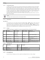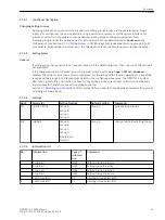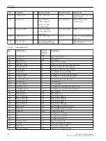
No.
Information
Type of
Informa-
tion
Comments
563
CB Alarm Supp
OUT
CB alarm suppressed
590
Line closure
OUT
Line closure detected
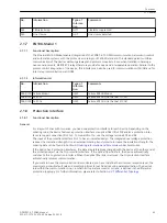
EN100-Modul 1
Functional Description
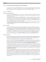
The Ethernet EN100-Modul enables integration of the 7SD80 in 100-Mbit communication networks in control
and automation systems with the protocols according to IEC 61850 standard. This standard permits uniform
communication of the devices without gateways and protocol converters. Even when installed in heteroge-
neous environments, SIPROTEC 4 relays therefore provide for open and interoperable operation. Parallel to the
process control integration of the device, this interface can also be used for communication with DIGSI and for
inter-relay communication via GOOSE.
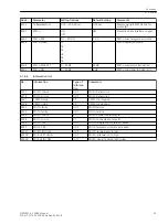
Information List
No.
Information
Type of
Informa-
tion
Comments
009.0100 Failure Modul
IntSP
Failure EN100 Modul
009.0101 Fail Ch1
IntSP
Failure EN100 Link Channel 1 (Ch1)
009.0102 Fail Ch2
IntSP
Failure EN100 Link Channel 2 (Ch2)
Protection Interface
Functional Description
General
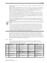
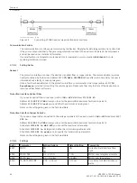
For a layout of lines with two ends, you need one protection interface for each device. Depending on the
ordering code, the device features a protection interface via optical fiber (Prot FO) and/or a protection inter-
face via copper connection (Prot Cu). To connect Prot Cu, use the voltage terminals D1 and D2.
The input of the protection interface Prot Cu has an insulated design. The integrated overvoltage protection
reduces the insulation strength. Use an external isolating transformer to increase the insulation strength. The
ordering data can be found in Section
A Ordering Information and Accessories
under Accessories.
If the device has 2 protection interfaces, the data are preferably exchanged with the device at the other end of
the protected object via the FO protection interface. If the optical fiber link fails, the device automatically
switches to the Cu protection interface. When the optical fiber link is restored, the FO protection interface
automatically resumes communication.
If you want to have the communication link monitored, you have to define the minimum reception level, the
maximum permissible fault rate and monitoring times for each device during parameterization. The device's
role within the communication line, i.e. whether it operates as master or slave, is defined in the differential
protection topology. For further information, please refer to Section
2.1.7
2.1.7.1
2.1.7.2
2.1.8
2.1.8.1
Functions
2.1 General
SIPROTEC 4, 7SD80, Manual
45
E50417-G1100-C474-A2, Edition 02.2018
Summary of Contents for SIPROTEC 4 7SD80
Page 8: ...8 SIPROTEC 4 7SD80 Manual E50417 G1100 C474 A2 Edition 02 2018 ...
Page 10: ...10 SIPROTEC 4 7SD80 Manual E50417 G1100 C474 A2 Edition 02 2018 ...
Page 18: ...18 SIPROTEC 4 7SD80 Manual E50417 G1100 C474 A2 Edition 02 2018 ...
Page 248: ...248 SIPROTEC 4 7SD80 Manual E50417 G1100 C474 A2 Edition 02 2018 ...
Page 298: ...298 SIPROTEC 4 7SD80 Manual E50417 G1100 C474 A2 Edition 02 2018 ...
Page 312: ...312 SIPROTEC 4 7SD80 Manual E50417 G1100 C474 A2 Edition 02 2018 ...
Page 322: ...322 SIPROTEC 4 7SD80 Manual E50417 G1100 C474 A2 Edition 02 2018 ...
Page 400: ...400 SIPROTEC 4 7SD80 Manual E50417 G1100 C474 A2 Edition 02 2018 ...
Page 402: ...402 SIPROTEC 4 7SD80 Manual E50417 G1100 C474 A2 Edition 02 2018 ...

