Thermal Overload Protection
The thermal overload protection prevents damage to the protected object caused by thermal overloading,
particularly in case of transformers, rotating machines, power reactors and cables. This protection is not appli-
cable to 1-phase busbar protection. It can be assigned to any of the sides of the main protected object,
however, not to a non-assigned measuring point.
General
Three methods of overload detection are available in 7UT6x:
•
Overload calculation using a thermal replica according to IEC 60255-8, without ambient temperature
influence
•
Overload calculation using a thermal replica according to IEC 60255-8, with ambient temperature influ-
ence
•
Calculation of the hot-spot temperature and determination of the ageing rate according to IEC 60354.
You may select one of these three methods. The first one is characterised by easy handling and setting; it
calculates the overtemperature caused by current heat losses.
For the second one the ambient or coolant temperature is taken into consideration; it calculates the total
temperature. It is required that the decisive coolant temperature is signalled to the device via a connected RTD
box.
The third needs some knowledge about the protected object and its thermal characteristics and the input of
the cooling medium temperature.
7UT6x is equipped with two breaker failure protection functions that can be used independent of each other
and for different locations of the protective object. One can also work with different starting criteria. The
assignment of the protective functions to the protected object are performed as described in Section
2.1.4.3 Assignment of Protection Functions to Measuring Locations / Sides
.
Overload Protection Using a Thermal Replica
Principle
The overload protection of 7UT6x can be assigned to one of the sides of the main protected object (select-
able). Since the cause of overload is normally outside the protected, the overload current is a through-flow
current.
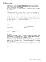
The unit computes the temperature rise according to a thermal single-body model as per the following
thermal differential equation
[thermueberl-differentialgleichung-021026-rei, 1, en_GB]
Θ
actual valid temperature rise referred to the final temperature rise at maximum
permissible current of the assigned side of the protected object k ·
Ι
NObj
τ
th
thermal time constant for the heating
k
k-factor which states the maximum permissible continuous current, referred to
the rated current of the assigned side of the protected object
Ι
currently valid RMS current of the assigned side of the protected object
Ι
NObj
rated current of the assigned side of the protected object
The protection function thus represents a thermal profile of the equipment being protected (overload protec-
tion with memory capability). Both the previous history of an overload and the heat loss to the environment
are taken into account.
2.9
2.9.1
2.9.2
Functions
2.9 Thermal Overload Protection
200
SIPROTEC 4, 7UT6x, Manual
C53000-G1176-C230-5, Edition 09.2016
Summary of Contents for SIPROTEC 4 7UT6 Series
Page 394: ...394 SIPROTEC 4 7UT6x Manual C53000 G1176 C230 5 Edition 09 2016 ...
Page 482: ...482 SIPROTEC 4 7UT6x Manual C53000 G1176 C230 5 Edition 09 2016 ...
Page 504: ...504 SIPROTEC 4 7UT6x Manual C53000 G1176 C230 5 Edition 09 2016 ...
Page 522: ...522 SIPROTEC 4 7UT6x Manual C53000 G1176 C230 5 Edition 09 2016 ...
Page 528: ...528 SIPROTEC 4 7UT6x Manual C53000 G1176 C230 5 Edition 09 2016 ...
Page 538: ...538 SIPROTEC 4 7UT6x Manual C53000 G1176 C230 5 Edition 09 2016 ...
Page 664: ...664 SIPROTEC 4 7UT6x Manual C53000 G1176 C230 5 Edition 09 2016 ...
Page 666: ...666 SIPROTEC 4 7UT6x Manual C53000 G1176 C230 5 Edition 09 2016 ...
Page 684: ...684 SIPROTEC 4 7UT6x Manual C53000 G1176 C230 5 Edition 09 2016 ...


