Differential Protection for Transformers
Matching of the Measured Values
In power transformers, generally, the secondary currents of the current transformers are not equal when a
current flows through the power transformer, but depend on the transformation ratio and the connection
group of the protected power transformer, and the rated currents of the current transformers. The currents
must therefore be matched in order to become comparable.
Matching to the various power transformer and current transformer ratios and of the phase displacement
according to the vector group of the protected transformer is performed purely mathematically. As a rule,
external matching transformers are not required.
The input currents are converted in relation to the power transformer rated currents. This is achieved by
entering the rated transformer data, such as rated power, rated voltage and rated primary currents of the
current transformers, into the protection device (Subsection “General Power System Data” under margin
heading “Object Data with Transformers”, and “Current Transformer Data for 3-phase Measuring Locations”).
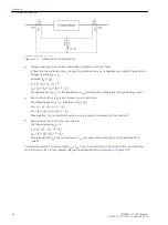
shows an example of magnitude matching. The primary nominal currents of the two sides (wind-
ings) S1 (378 A) and S2 (1663 A) are calculated from the rated apparent power of the transformer (72 MVA)
and the nominal voltages of the windings (110 kV and 25 kV). Since the nominal currents of the current trans-
formers deviate from the nominal currents of the power transformer sides, the secondary currents are multi-
plied with the factors k1 and k2. After this matching, equal current magnitudes are achieved at both sides
under nominal conditions of the power transformer.
[betraganpassung-bsp-2wick-trans280503-st, 1, en_GB]
Figure 2-26
Magnitude matching — example of a two-winding power transformer (phase relation not
considered)
Concerning power transformers with more than two windings, the windings may have different power
ratings. In order to achieve comparable currents for the differential protection, all currents are referred to the
winding (= side) with the highest power rating. This apparent power is named the rated power of the
protected object.
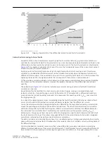
shows an example of a three-winding power transformer. Winding 1 (S1) and 2 (S2) are rated for
72 MVA; The settings recommended are the same as in
. But the third winding (S3) has 16 MVA
rating (e.g. for auxiliary supply). The rated current of this winding (= side of the protected object) results in
924 A. On the other hand, the differential protection has to process comparable currents. Therefore, the
currents of this winding must be referred to the rated power of the protected object, i.e. 72 MVA. This results
in a rated current (i.e. the current under nominal conditions of the protected object, 72 MVA) of 4157 A. This
is the base value for the third winding: These currents must be multiplied by the factor k3.
2.2.2
Functions
2.2 Differential Protection
SIPROTEC 4, 7UT6x, Manual
101
C53000-G1176-C230-5, Edition 09.2016
Summary of Contents for SIPROTEC 4 7UT6 Series
Page 394: ...394 SIPROTEC 4 7UT6x Manual C53000 G1176 C230 5 Edition 09 2016 ...
Page 482: ...482 SIPROTEC 4 7UT6x Manual C53000 G1176 C230 5 Edition 09 2016 ...
Page 504: ...504 SIPROTEC 4 7UT6x Manual C53000 G1176 C230 5 Edition 09 2016 ...
Page 522: ...522 SIPROTEC 4 7UT6x Manual C53000 G1176 C230 5 Edition 09 2016 ...
Page 528: ...528 SIPROTEC 4 7UT6x Manual C53000 G1176 C230 5 Edition 09 2016 ...
Page 538: ...538 SIPROTEC 4 7UT6x Manual C53000 G1176 C230 5 Edition 09 2016 ...
Page 664: ...664 SIPROTEC 4 7UT6x Manual C53000 G1176 C230 5 Edition 09 2016 ...
Page 666: ...666 SIPROTEC 4 7UT6x Manual C53000 G1176 C230 5 Edition 09 2016 ...
Page 684: ...684 SIPROTEC 4 7UT6x Manual C53000 G1176 C230 5 Edition 09 2016 ...


