Time Overcurrent Protection for Earth Current
General
The time overcurrent protection for earth current is assigned to a 1-phase measured current input of the
device. It can be used for any desired single-phase application. Its preferred application is the detection of an
earth current between the starpoint of a protective object and its earth electrode (that's why the description).
The corresponding one-phase additional measuring input has to be correctly assigned to the one-phase
current transformer of the power plant.
This protection can be used in addition to the restricted earth fault protection (Section
). Then it forms the backup protection for earth faults outside the protected zone which are
not cleared there.
The time overcurrent protection for earth current provides two definite time stages (O) and one inverse time
stage (C). The latter may operate according to an IEC or an ANSI, or a user defined characteristic.
[ueb-erd-reservesch-020926-st, 1, en_GB]
Figure 2-79
Time overcurrent protection as backup protection for restricted earth fault protection
7UT612 is equipped with one, 7UT613/63x with two time overcurrent protection functions that can be used
independently of each other and for different locations. Allocation of the respective protection functions to
the single-phase measuring locations were done according to Section
2.1.4.3 Assignment of Protection Func-
tions to Measuring Locations / Sides
.
Definite Time, Instantaneous Overcurrent Protection
The definite time stages (O) for earth current are always available even if an inverse time characteristic has
been configured in the scope of functions (see Section
Pickup, Trip
Two definite time stages are available for the earth current.
For the IE>> stage, the current measured at the assigned 1-phase current input is compared with the setting
value
IE>>
. Current above the pickup value is detected and annunciated. When the delay time
T IE>>
has
expired, tripping command is issued. The reset value is approximately 95 % below the pickup value for
currents above
Ι
N
. Lower values require a higher hysteresis in order to avoid intermittent pickup on currents
near the pickup value (e.g. 20 % at 0.1 ·
Ι
N
).
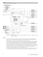
The following figure shows the logic diagram for the high-current stage
IE>>
.
2.5
2.5.1
2.5.2
Functions
2.5 Time Overcurrent Protection for Earth Current
SIPROTEC 4, 7UT6x, Manual
161
C53000-G1176-C230-5, Edition 09.2016
Summary of Contents for SIPROTEC 4 7UT6 Series
Page 394: ...394 SIPROTEC 4 7UT6x Manual C53000 G1176 C230 5 Edition 09 2016 ...
Page 482: ...482 SIPROTEC 4 7UT6x Manual C53000 G1176 C230 5 Edition 09 2016 ...
Page 504: ...504 SIPROTEC 4 7UT6x Manual C53000 G1176 C230 5 Edition 09 2016 ...
Page 522: ...522 SIPROTEC 4 7UT6x Manual C53000 G1176 C230 5 Edition 09 2016 ...
Page 528: ...528 SIPROTEC 4 7UT6x Manual C53000 G1176 C230 5 Edition 09 2016 ...
Page 538: ...538 SIPROTEC 4 7UT6x Manual C53000 G1176 C230 5 Edition 09 2016 ...
Page 664: ...664 SIPROTEC 4 7UT6x Manual C53000 G1176 C230 5 Edition 09 2016 ...
Page 666: ...666 SIPROTEC 4 7UT6x Manual C53000 G1176 C230 5 Edition 09 2016 ...
Page 684: ...684 SIPROTEC 4 7UT6x Manual C53000 G1176 C230 5 Edition 09 2016 ...


