Function Control
The function logic coordinates the sequence of both the protective and ancillary functions, processes the func-
tional decisions, and data received from the system.
Pickup Logic for the Entire Device
General Device Pickup
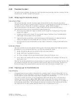
The fault detection logic combines the pickup signals of all protection functions. The pickup signals are
combined with OR and lead to a general pickup of the device. It is signalled with the alarm
Relay PICKUP
. If
a protection function of the device is not picked up any longer,
Relay PICKUP
disappears.
General fault detection is a requirement for a series of internal and external subsequent functions.
Among these functions, which are controlled by the general pickup, are:
•
Start of a fault log: All fault messages are entered into the trip log from the beginning of the general
pickup to the dropout.
•
Initialization of the fault recording: The recording and storage of fault wave forms can additionally be
made subject to the presence of a trip command.
•
Creation of spontaneous displays: Certain fault messages can be displayed as so-called spontaneous
displays. This display can be made dependent on occurrence of a trip command.
•
External functions can be controlled via an output contact. Examples are: starting of additional devices,
or similar.
Spontaneous Displays
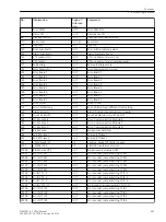
Spontaneous indications are fault indications which appear in the display automatically following a general
fault detection or trip command of the device. For 7UT6x, these indications include:
•
Relay PICKUP
: the pickup of a protection function with phase indication;
•
Relay TRIP
: trip of any protection function;
•
PU Time
: = running time from general device pickup to dropout of the device, in ms;
•
Trip time
: = the operating time from the general pickup to the first trip command of the device, the
time is given in ms.
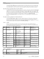
Note that the overload protection does not have a pickup in comparison to the other protective functions. The
general device pickup time (PU Time) is started with the trip signal, which starts the trip log. The dropout of
the thermal image of the overload protection ends the fault case and, thereby the running PU Time.
Tripping Logic for the Entire Device
General Tripping
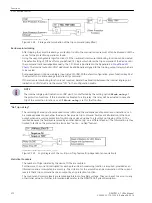
All tripping signals of the protection functions are OR–combined and lead to the alarm “Relay TRIP”. This can
be allocated to an LED or output relay as can be each of the individual trip commands. It is suitable as general
trip information as well as used for the output of trip commands to the circuit breaker.
Once a trip command is activated, it is stored separately for each protection function. At the same time a
minimum trip command duration
TMin TRIP CMD
is started to ensure that the command is sent to the
circuit breaker long enough if the tripping protection function should drop off too quickly or if the breaker of
the feeding end operates faster. The trip commands cannot be terminated until the last protection function
has dropped off (no function activated) AND the minimum trip command duration is over.
2.20
2.20.1
2.20.2
Functions
2.20 Function Control
SIPROTEC 4, 7UT6x, Manual
271
C53000-G1176-C230-5, Edition 09.2016
Summary of Contents for SIPROTEC 4 7UT6 Series
Page 394: ...394 SIPROTEC 4 7UT6x Manual C53000 G1176 C230 5 Edition 09 2016 ...
Page 482: ...482 SIPROTEC 4 7UT6x Manual C53000 G1176 C230 5 Edition 09 2016 ...
Page 504: ...504 SIPROTEC 4 7UT6x Manual C53000 G1176 C230 5 Edition 09 2016 ...
Page 522: ...522 SIPROTEC 4 7UT6x Manual C53000 G1176 C230 5 Edition 09 2016 ...
Page 528: ...528 SIPROTEC 4 7UT6x Manual C53000 G1176 C230 5 Edition 09 2016 ...
Page 538: ...538 SIPROTEC 4 7UT6x Manual C53000 G1176 C230 5 Edition 09 2016 ...
Page 664: ...664 SIPROTEC 4 7UT6x Manual C53000 G1176 C230 5 Edition 09 2016 ...
Page 666: ...666 SIPROTEC 4 7UT6x Manual C53000 G1176 C230 5 Edition 09 2016 ...
Page 684: ...684 SIPROTEC 4 7UT6x Manual C53000 G1176 C230 5 Edition 09 2016 ...

