AnalogOutputs
Depending on the variant ordered, the 7VE61 and 7VE63 parallel switching devices can have up to four analog
outputs (plug-in modules on ports B and D). The analog outputs determine the output of percentage meas-
ured values which are made available by the synchronization function.
Functional Description
Application
The synchronizing function measured values to be transmitted via these analog outputs have been specified
during function scope configuration (see Section
). Up to four of the following analog
outputs are available:
•
Masure value ΔU as a percentage of the operational rated voltage U
Nom
,
•
Measured value Δf as a percentage of the rated frequency f
Nom
,
•
Measured value Δα as a percentage of 180°,
•
Measure value |ΔU| as a percentage of the operational rated voltage U
Nom
,
•
Measured value |Δf| as a percentage of the rated frequency f
Nom
,
•
Measured value |Δα| as a percentage of 180°,
•
Measured value U1 as a percentage of the operational rated voltage U
Nom
•
Measured value U2 as a percentage of the operational rated voltage U
Nom
•
Measured value f1 as a percentage of the rated frequency f
Nom
•
Measured value f2 as a percentage of the rated frequency f
Nom
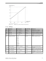
Analog values are output as injected currents. The analog outputs have a nominal range between 0 mA and
20 mA, their operating range can be up to 22.5 mA. The conversion factor and the validity range can be set.
If measured values are transmitted, they are cyclically updated 1× per cycle.
Setting Notes
General
You have specified during configuration of the analog outputs (Section
to 176), which of the analog inputs available in the device are to be used. If a function is not needed,
Disa-
bled
is set. The other parameters associated with this analog output are masked out in such a case.
i
i
NOTE
The measured values are produced by the synchronizing function. If no synchronizing function group is
activated or if all synchronizing function groups are set to
Disabled
or
OFF
no measured values are
generated.
Measured Values
Once the measured values are selected for the analog outputs (Section
, addresses 173
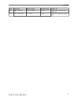
to 176), set the conversion factors for the available outputs under addresses 7301 to 7305, as follows:
•
Scaling factor U:
Address 7301
SCAL. U
= value in V, which corresponds to 100 %,
•
Scaling factor frequency:
Address 7302
SCAL. f
= value in Hz, which corresponds to 100 %,
2.11
2.11.1
2.11.2
Functions
2.11 AnalogOutputs
106
SIPROTEC 4, 7VE61 and 7VE63, Manual
C53000-G1176-C163-3, Edition 10.2017
Summary of Contents for SIPROTEC 4 7VE61
Page 8: ...8 SIPROTEC 4 7VE61 and 7VE63 Manual C53000 G1176 C163 3 Edition 10 2017 ...
Page 24: ...24 SIPROTEC 4 7VE61 and 7VE63 Manual C53000 G1176 C163 3 Edition 10 2017 ...
Page 142: ...142 SIPROTEC 4 7VE61 and 7VE63 Manual C53000 G1176 C163 3 Edition 10 2017 ...
Page 192: ...192 SIPROTEC 4 7VE61 and 7VE63 Manual C53000 G1176 C163 3 Edition 10 2017 ...
Page 222: ...222 SIPROTEC 4 7VE61 and 7VE63 Manual C53000 G1176 C163 3 Edition 10 2017 ...
Page 230: ...230 SIPROTEC 4 7VE61 and 7VE63 Manual C53000 G1176 C163 3 Edition 10 2017 ...
Page 256: ...256 SIPROTEC 4 7VE61 and 7VE63 Manual C53000 G1176 C163 3 Edition 10 2017 ...
Page 314: ...314 SIPROTEC 4 7VE61 and 7VE63 Manual C53000 G1176 C163 3 Edition 10 2017 ...
Page 316: ...316 SIPROTEC 4 7VE61 and 7VE63 Manual C53000 G1176 C163 3 Edition 10 2017 ...
Page 330: ...330 SIPROTEC 4 7VE61 and 7VE63 Manual C53000 G1176 C163 3 Edition 10 2017 ...

