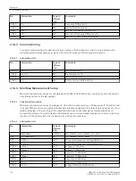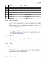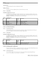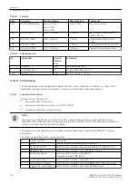
are sampled at intervals of 1 ms (for 50 Hz) or 1.04 ms (for 60 Hz), and stored in a ring buffer (20 samples per
cycle). For a fault, the data are recorded for a set period of time, but not for more than 10 seconds.
The rms values of measured values
U1, U2, f1, f2, ΔU, Δf, Δα
can be deposited in a ring buffer, one measured value per half cycle. For a fault, the data are recorded for a set
period of time, but not for more than 100 seconds.
Up to 8 fault records can be recorded in this buffer. The fault record memory is automatically updated with
every new fault, so no acknowledgment is required. The fault record buffer can also be started via binary
input, integrated operator interface or via serial interface.
The data can be retrieved via the serial interfaces by means of a personal computer and evaluated with the
protection data processing program DIGSI and the graphic analysis software SIGRA. The latter graphically
processes the data recorded during the system fault. Signals are additionally recorded as binary tracks (marks)
e.g. “Pickup”, “Trip”, “CLOSE Command”, “Balancing Commands” among others.
If the device has a serial system interface (IEC 60870–5–103), fault recording data can be passed on to a
central device (e.g. SICAM) via this interface. Data are evaluated by appropriate programs in the central
device. Voltages are referred to their maximum values, scaled to their rated values and prepared for graphic
presentation. Binary signal traces (marks) are also recorded.
Transfer to a central device can be polled automatically, either after each fault detection by the protection, or
only after a trip.
Setting Notes
Fault Recording
Fault recording (waveform capture) will only take place if address was set to 104
FAULT VALUE
=
Instant.
values
or
RMS values
. Other settings pertaining to fault recording (waveform capture) are found in the
OSC. FAULT REC. submenu of the PARAMETER menu. Waveform capture makes a distinction between the
trigger for an oscillographic record and the criterion to save the record (address 401
WAVEFORMTRIGGER
).
Normally the trigger is the pickup of a protective element, i.e. when a protective element picks up the time is
0. The criterion for saving may be both the device pickup (
Save w. Pickup
) or the device trip (
Save w.
TRIP
). A trip command issued by the device can also be used as trigger instant (
Start w. TRIP
); in this
case it is also the saving criterion.
For the synchronising functions, two trigger criteria are likewise established. The indication
Syx running
(170.2022) corresponds to the “protection pickup”. It is forced when the synchronizing function is started. The
“protection tripping” corresponds to triggering with the CLOSE command. With the
1
/
2
- and 2-channel version
this is the AND combination Sync CloseRel 1 & Sync CloseRel 2.
If the course of the CLOSE command is to be always recorded the setting
Start w. TRIP
is selected.
In 7VE61 and 7VE63, a waveform capture includes the complete course of a fault. Recording of an oscillo-
graphic fault record starts with the pickup by a protective function and ends with the dropout of the last
pickup of a protective function.
The actual storage time encompasses the pre-fault time
PRE. TRIG. TIME
(address 404) ahead of the refer-
ence instant and and ends at the post-fault time
POST REC. TIME
(address 405) after the storage criterion
has reset. The maximum recording duration to each fault (
MAX. LENGTH
) is set at address 403. The setting
depends on the criterion for storage, the delay time of the protective functions and the desired number of
stored fault events. The largest value here is 10 s for fault recording of instantaneous values, 100 s for
recording of r.m.s. values (see address 104). A total of 8 records can be saved in this time.
Note: These times apply for 50 Hz. They will be different with another frequency. If
RMS values
are stored,
the times stated for parameters 403 to 406 will be 10 times longer.
An oscillographic record can be triggered by a change in status of a binary input, or through the operating
interface via PC. Storage is then triggered dynamically. The length of a record for these special triggers is set at
address 406
BinIn CAPT.TIME
(upper bound is
MAX. LENGTH
, address 403). Pre- and post-fault times
must still be added. If the binary input time is set to 8 , then the length of the record equals the time that the
binary input is activated (static), or the
MAX. LENGTH
(address 403), whichever is shorter.
2.14.8.2
Functions
2.14 Auxiliary Functions
SIPROTEC 4, 7VE61 and 7VE63, Manual
127
C53000-G1176-C163-3, Edition 10.2017
Summary of Contents for SIPROTEC 4 7VE61
Page 8: ...8 SIPROTEC 4 7VE61 and 7VE63 Manual C53000 G1176 C163 3 Edition 10 2017 ...
Page 24: ...24 SIPROTEC 4 7VE61 and 7VE63 Manual C53000 G1176 C163 3 Edition 10 2017 ...
Page 142: ...142 SIPROTEC 4 7VE61 and 7VE63 Manual C53000 G1176 C163 3 Edition 10 2017 ...
Page 192: ...192 SIPROTEC 4 7VE61 and 7VE63 Manual C53000 G1176 C163 3 Edition 10 2017 ...
Page 222: ...222 SIPROTEC 4 7VE61 and 7VE63 Manual C53000 G1176 C163 3 Edition 10 2017 ...
Page 230: ...230 SIPROTEC 4 7VE61 and 7VE63 Manual C53000 G1176 C163 3 Edition 10 2017 ...
Page 256: ...256 SIPROTEC 4 7VE61 and 7VE63 Manual C53000 G1176 C163 3 Edition 10 2017 ...
Page 314: ...314 SIPROTEC 4 7VE61 and 7VE63 Manual C53000 G1176 C163 3 Edition 10 2017 ...
Page 316: ...316 SIPROTEC 4 7VE61 and 7VE63 Manual C53000 G1176 C163 3 Edition 10 2017 ...
Page 330: ...330 SIPROTEC 4 7VE61 and 7VE63 Manual C53000 G1176 C163 3 Edition 10 2017 ...

