•
Filtering and preparation of the measured quantities
•
Continuous monitoring of the measured quantities
•
Processing of the algorithms for the synchrocheck function
•
Monitoring of the pickup conditions for the individual protective functions
•
Interrogation of limit values and sequences in time
•
Controlling signals for logic functions
•
Output of control commands for switching devices
•
Signalling of synchronization and protection behaviour via LEDs, LCD, relays or serial interfaces
•
Recording of messages, fault data and fault values for analysis
•
Management of the operating system and the associated functions such as data recording, real-time
clock, communication, interfaces, etc.
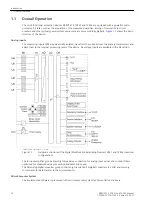
Binary Inputs and Outputs
Binary inputs and outputs from and to the computer system are routed via the I/O modules (inputs and
outputs). The computer system obtains the information from the system (e.g remote resetting) or the external
equipment (e.g. blocking commands). Outputs are mainly commands that are issued to the switching devices
and messages for remote signalling of events and states.
Front Elements
Light-emitting diodes (LEDs) and a display (LCD) on the front panel provide information on the functional
status of the device and report events, states and measured values. The integrated control keys and numeric
keys in conjunction with the LCD enable local interaction with the device. They allow the user to retrieve any
kind of information from the device such as configuration and setting parameters, operational indications and
fault messages (see also
) and to change setting parameters.
Serial Interfaces
A personal computer running the DIGSI software can be connected to the serialoperator interface (PC port) on
the front panel to conveniently operate all device functions.
A separate service interface can be provided for remote communication with the device via a personal
computer using DIGSI 4. This interface is especially well suited for a permanent connection of the devices to
the PC or for operation via a modem.
All data can be transferred to a central control or monitoring system via the serial system interface. Various
protocols and physical arrangements are available for this interface to suit the particular application.
A further interface is provided for time synchronization of the internal clock through external synchronization
sources.
Further communication protocols can be implemented via additional interface modules.
Analog Outputs
Depending on the ordering variant and configuration, ports B and D can be equipped with analog output
modules for the output of selected measured values (0 to 20 mA or 4 to 20 mA).
Power Supply
The functional units described are supplied by a power supply PS with the necessary power in the different
voltage levels. Voltage dips may occur if the voltage supply system (substation battery) becomes short-
circuited. Usually, they are bridged by a capacitor (see also Technical Data).
Introduction
1.1 Overall Operation
SIPROTEC 4, 7VE61 and 7VE63, Manual
17
C53000-G1176-C163-3, Edition 10.2017
Summary of Contents for SIPROTEC 4 7VE61
Page 8: ...8 SIPROTEC 4 7VE61 and 7VE63 Manual C53000 G1176 C163 3 Edition 10 2017 ...
Page 24: ...24 SIPROTEC 4 7VE61 and 7VE63 Manual C53000 G1176 C163 3 Edition 10 2017 ...
Page 142: ...142 SIPROTEC 4 7VE61 and 7VE63 Manual C53000 G1176 C163 3 Edition 10 2017 ...
Page 192: ...192 SIPROTEC 4 7VE61 and 7VE63 Manual C53000 G1176 C163 3 Edition 10 2017 ...
Page 222: ...222 SIPROTEC 4 7VE61 and 7VE63 Manual C53000 G1176 C163 3 Edition 10 2017 ...
Page 230: ...230 SIPROTEC 4 7VE61 and 7VE63 Manual C53000 G1176 C163 3 Edition 10 2017 ...
Page 256: ...256 SIPROTEC 4 7VE61 and 7VE63 Manual C53000 G1176 C163 3 Edition 10 2017 ...
Page 314: ...314 SIPROTEC 4 7VE61 and 7VE63 Manual C53000 G1176 C163 3 Edition 10 2017 ...
Page 316: ...316 SIPROTEC 4 7VE61 and 7VE63 Manual C53000 G1176 C163 3 Edition 10 2017 ...
Page 330: ...330 SIPROTEC 4 7VE61 and 7VE63 Manual C53000 G1176 C163 3 Edition 10 2017 ...

