Checking the Synchrocheck
Hierzu sind die gleichen Prüfschritte, wie bei der Synchronisierfunktion durchzuführen (siehe oben). In der
Variante
1ph Sync check
wird für jede Seite nur eine Spannung benutzt. Es entfällt damit die Drehfeldkon-
trolle.
Measuring the Operating Time of the Circuit Breaker
General
In order to achieved an exact parallel switching with a zero phase angle, it is necessary – under asynchronous
system conditions – that the operating time of the circuit breaker is measured and set correctly when closing.
If it is switched exclusively with synchronism systems conditions, this section can be skipped.
With External Timer
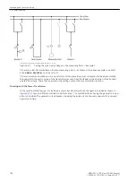
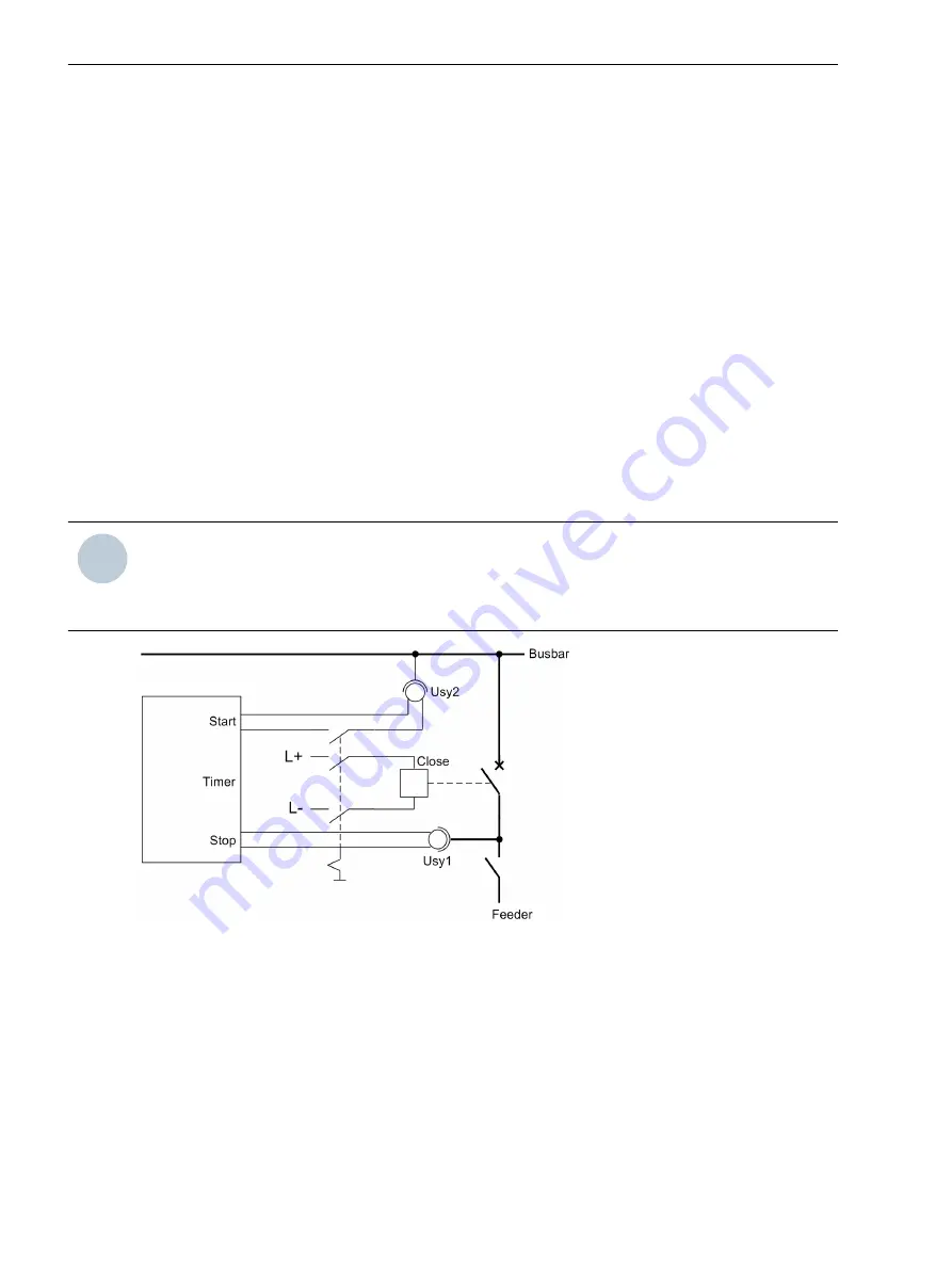
For measuring the operating time a setup as shown in
is recommended. The timer is set to a range
of 1 s and a graduation of 1 ms.
The circuit breaker is connected manually. At the same time the timer is started. After closing the poles of the
circuit breaker, the voltage U
Line
appears and the timer is stopped.
If the timer is not stopped due to an unfavourable closing moment, the attempt will be repeated.
It is particularly favourable to calculate the mean value from several (3 to 5) successful switching attempts.
i
i
NOTE
You may add to the measured value the operating time of the parallel switching device (22 ms at f
N
= 50 or
60 Hz; 42 ms at f
N
= 16.7 Hz) and set the total length of time under address 6120 as
T-CB close
. Round
off to the next lower settable value. Proceed for all used synchronizing functions 2 to 8 in the same way.
[messung-der-ls-eigenzeit-260602-kn, 1, en_GB]
Figure 3-24
Measuring the circuit breaker closing time
By Reading Out from Fault Records
The circuit breaker closing time can be also determined by reading out fault records in respect to the time
delay between the CLOSE command to the circuit breaker and the closing of the circuit breaker poles. In such
case, the obtained time from the fault record is the real circuit breaker closing time.
To do so, the following procedure is recommended:
•
Set a similar state which can be switched with no danger of the circuit breaker.
•
Activate the parameter 6107
SYNC U1<U2>
in the synchronization functional group 1 setting to
YES
, if
U2 is switched. The setting for the parameter 6108
SYNC U1>U2<
=
YES
applies when switching
through to U1.
3.3.9
Mounting and Commissioning
3.3 Commissioning
182
SIPROTEC 4, 7VE61 and 7VE63, Manual
C53000-G1176-C163-3, Edition 10.2017
Summary of Contents for SIPROTEC 4 7VE61
Page 8: ...8 SIPROTEC 4 7VE61 and 7VE63 Manual C53000 G1176 C163 3 Edition 10 2017 ...
Page 24: ...24 SIPROTEC 4 7VE61 and 7VE63 Manual C53000 G1176 C163 3 Edition 10 2017 ...
Page 142: ...142 SIPROTEC 4 7VE61 and 7VE63 Manual C53000 G1176 C163 3 Edition 10 2017 ...
Page 192: ...192 SIPROTEC 4 7VE61 and 7VE63 Manual C53000 G1176 C163 3 Edition 10 2017 ...
Page 222: ...222 SIPROTEC 4 7VE61 and 7VE63 Manual C53000 G1176 C163 3 Edition 10 2017 ...
Page 230: ...230 SIPROTEC 4 7VE61 and 7VE63 Manual C53000 G1176 C163 3 Edition 10 2017 ...
Page 256: ...256 SIPROTEC 4 7VE61 and 7VE63 Manual C53000 G1176 C163 3 Edition 10 2017 ...
Page 314: ...314 SIPROTEC 4 7VE61 and 7VE63 Manual C53000 G1176 C163 3 Edition 10 2017 ...
Page 316: ...316 SIPROTEC 4 7VE61 and 7VE63 Manual C53000 G1176 C163 3 Edition 10 2017 ...
Page 330: ...330 SIPROTEC 4 7VE61 and 7VE63 Manual C53000 G1176 C163 3 Edition 10 2017 ...


