Asynchronous Systems
The generator is placed to a speed below the permissible frequency difference via manual control according to
6132
df ASYN f2>f1
or 6133
df ASYN f2<f1
. The generator is activated to the system voltage. The
values can be read out in the operational measured values in the 7VE61 and 7VE63.
The synchronization function is initiated in the 7VE61 and 7VE63 (e.g. per start input or measurement request
via the integrated control using the control keys). If there is a synchroscope available, initiation takes place
approximately by synchronism , thus “12 o´clock”; then the duration is equivalent command to a revolution
for a duration of 1/Δf until the parallel switching command (with a frequency difference of 0.1 Hz therefore 10
s).
This attempt is several times executed for oversynchronous switching and for undersynchronous switching —
if it is permissible for both.
The switching on behaviour is checked with an external recorder or with the integrated fault record function.
Additionally both procedures must have issued the CLOSE command briefly before the synchronous instant,
with offset to the close time of the circuit breaker.
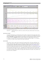
shows an example of an instantaneous value
recording. The envelope curve and the synchronous instance are clearly visible as well as the binary tracks
traces with the CLOSE commands of the two measuring procedures. The track with the difference angle Δα is
to be used for the evaluation of the switching on behaviour. The distance between the CLOSE command and
Δα = 0 must correspond to the circuit breaker closing time. The circuit breaker closing time of the circuit
breaker runs in the example to 420 ms. In case of long time, there was an interlocking switched in between.
[ve6-momentanwertschrieb-asnchron-210503-kn, 1, en_GB]
Figure 3-26
Record of instantaneous values from a generator synchronization (asynchronous conditions)
The test operation with the synchronization function can be repeated at the limits of the permissible voltage
difference.
The correct function of the setpoint commands is then checked for devices with frequency and voltage
balancer. In addition the setpoint command circuits can be switched active (connected again); the close
command remains interrupted.
The generator is started with a speed outside the area for the asynchronous switching. The synchronization
function is initiated.
Mounting and Commissioning
3.3 Commissioning
184
SIPROTEC 4, 7VE61 and 7VE63, Manual
C53000-G1176-C163-3, Edition 10.2017
Summary of Contents for SIPROTEC 4 7VE61
Page 8: ...8 SIPROTEC 4 7VE61 and 7VE63 Manual C53000 G1176 C163 3 Edition 10 2017 ...
Page 24: ...24 SIPROTEC 4 7VE61 and 7VE63 Manual C53000 G1176 C163 3 Edition 10 2017 ...
Page 142: ...142 SIPROTEC 4 7VE61 and 7VE63 Manual C53000 G1176 C163 3 Edition 10 2017 ...
Page 192: ...192 SIPROTEC 4 7VE61 and 7VE63 Manual C53000 G1176 C163 3 Edition 10 2017 ...
Page 222: ...222 SIPROTEC 4 7VE61 and 7VE63 Manual C53000 G1176 C163 3 Edition 10 2017 ...
Page 230: ...230 SIPROTEC 4 7VE61 and 7VE63 Manual C53000 G1176 C163 3 Edition 10 2017 ...
Page 256: ...256 SIPROTEC 4 7VE61 and 7VE63 Manual C53000 G1176 C163 3 Edition 10 2017 ...
Page 314: ...314 SIPROTEC 4 7VE61 and 7VE63 Manual C53000 G1176 C163 3 Edition 10 2017 ...
Page 316: ...316 SIPROTEC 4 7VE61 and 7VE63 Manual C53000 G1176 C163 3 Edition 10 2017 ...
Page 330: ...330 SIPROTEC 4 7VE61 and 7VE63 Manual C53000 G1176 C163 3 Edition 10 2017 ...

