General
The settings associated with the various device functions may be modified by using the operating or service
interface in DIGSI. The procedure is set out in detail in the
uration parameters in the device, password no. 7 (for parameter set; default setting: 000000) is required.
Without the password, the settings may be read, but may not be modified and transmitted to the device.
The settings associated with the various device functions, limit values, etc. can be modified using the controls
on the front panel of the device or by using the operator interface with DIGSI in conjunction with a personal
computer. Password No. 5 (for single parameter; default setting: 000000).
Device
The device can issue a serie of general annunciations about itself and the substation. These annunciations are
listed in the following information list. Most annunciations are self-explanatory. The special cases are
described below:
Reset: Device is reset on each Power ON.
Initial Start: Initial start occurs after initialization of the device by DIGSI.
Restart: Restart occurs after loading a parameter set or after reset.
The indication of messages masked to LEDs, and the maintenance of spontaneous messages, can be made
dependent on whether the device has issued a trip command. In this situation, messages are not reported, if
one or more protective functions have picked up on a fault, but a trip signal has not been issued yet by the
7VE61 and 7VE63, because the fault was cleared by another device (for example, outside the own protection
range). These messages are then limited to faults in the line to be protected.
Setting Notes
Spontaneous Fault Display
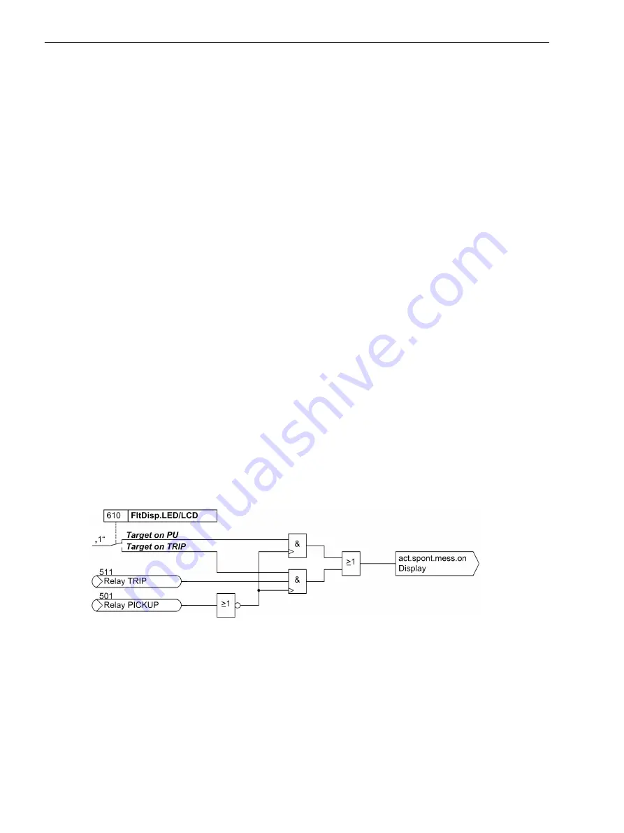
After a fault has occurred, the device display spontaneously shows the most important fault data. In address
610
FltDisp.LED/LCD
you can select whether the spontaneous fault display is updated for each fault
(
Target on PU
) or only for faults that included a trip (
Target on TRIP
).
For devices with graphical display use parameter 611
Spont. FltDisp.
to specify whether a spontaneous
fault display will be shown automatically
YES
) or not (
NO
). For devices featuring a text display such displays
will always appear a power system fault.
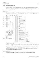
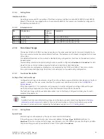
[logik-spondanmeld-display-081024, 1, en_GB]
Figure 2-1
Generation of spontaneous fault indications on the display
Resetting stored LEDs / relays
A new pickup will generally erase any stored LEDs/relays so that only the latest fault information is displayed at
any time. A time can be set in address 615
T MIN LED HOLD
during which the stored LEDs and relays will
not be deleted. Any information occurring during that period of time will be linked via OR.
The option
Target on TRIP
in address 610
FltDisp.LED/LCD
allows you to delete the information of the
most recent fault stored on LEDs and relays provided that this fault has not resulted in a trip command of the
device.
2.1
2.1.1
2.1.1.1
Functions
2.1 General
26
SIPROTEC 4, 7VE61 and 7VE63, Manual
C53000-G1176-C163-3, Edition 10.2017
Summary of Contents for SIPROTEC 4 7VE61
Page 8: ...8 SIPROTEC 4 7VE61 and 7VE63 Manual C53000 G1176 C163 3 Edition 10 2017 ...
Page 24: ...24 SIPROTEC 4 7VE61 and 7VE63 Manual C53000 G1176 C163 3 Edition 10 2017 ...
Page 142: ...142 SIPROTEC 4 7VE61 and 7VE63 Manual C53000 G1176 C163 3 Edition 10 2017 ...
Page 192: ...192 SIPROTEC 4 7VE61 and 7VE63 Manual C53000 G1176 C163 3 Edition 10 2017 ...
Page 222: ...222 SIPROTEC 4 7VE61 and 7VE63 Manual C53000 G1176 C163 3 Edition 10 2017 ...
Page 230: ...230 SIPROTEC 4 7VE61 and 7VE63 Manual C53000 G1176 C163 3 Edition 10 2017 ...
Page 256: ...256 SIPROTEC 4 7VE61 and 7VE63 Manual C53000 G1176 C163 3 Edition 10 2017 ...
Page 314: ...314 SIPROTEC 4 7VE61 and 7VE63 Manual C53000 G1176 C163 3 Edition 10 2017 ...
Page 316: ...316 SIPROTEC 4 7VE61 and 7VE63 Manual C53000 G1176 C163 3 Edition 10 2017 ...
Page 330: ...330 SIPROTEC 4 7VE61 and 7VE63 Manual C53000 G1176 C163 3 Edition 10 2017 ...

