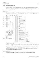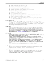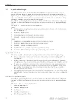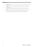
Parameter 104
FAULT VALUE
is used to specify whether the oscillographic fault recording should record
Instant. values
or
RMS values
. If
RMS values
are stored, the available recording time increases by
the factor 10.
The parameter 145
df/dt Protect.
establishes for the frequency change protection whether this is to
contain two or four stages or is
Disabled
.
Up to 8 SYNC function groups are available for the synchronizing function. They are enabled in addresses 016x
(x = 1 ... 8). Parameters 161
SYNC function 1
to 168
SYNC function 8
are used in addition to preselect
the mode of operation:
1ph Sync check
corresponds to the classical synchronizing function with in each case single-phase connec-
tion of the voltages to be compared.
3ph Sync check
corresponds to the classical synchronizing function with in each case multi-phase connec-
tion of the voltages to be compared.
i
i
NOTE
A mixed parametrization of single-phase and three-phase synchrocheck between function groups is inad-
missible and leads to an error indication.
1,5chan.Synchr
with the 7VE61 or
2chan.Synchr.
with the 7VE63 corresponds to operation as a parallel
device. Connection is multiphase, processing of data command issuing is done 1
1
/
2
-channel with the 7VE61 or
2-channel with the 7VE63.
i
i
NOTE
A mixed parametrization of three-phase synchrocheck and 1
1
/
2
or 2-channel synchronising function is
possible due to the identical connection.
If a function is not needed,
Disabled
is set. A synchronizing function group thus rendered ineffective is
excluded in the menu item Synchronization, all other groups are displayed. The maximum number of the
existing synchronising function groups is established by the device variant (see section “Function description
of the synchronizing function”).
Settings
Addr.
Parameter
Setting Options
Default Setting
Comments
103
Grp Chge OPTION
Disabled
Enabled
Disabled
Setting Group Change Option
104
FAULT VALUE
Disabled
Instant. values
RMS values
RMS values
Fault values
140
UNDERVOLTAGE
Disabled
Enabled
Enabled
Undervoltage Protection
141
OVERVOLTAGE
Disabled
Enabled
Enabled
Overvoltage Protection
142
FREQUENCY Prot.
Disabled
Enabled
Enabled
Over / Underfrequency Protection
145
df/dt Protect.
Disabled
2 df/dt stages
4 df/dt stages
2 df/dt stages
Rate-of-frequency-change protec-
tion
146
VECTOR JUMP
Disabled
Enabled
Enabled
Jump of Voltage Vector
160
BALANC. (MLFB)
Disabled
Enabled
Disabled
Balancing Commands (Siemens
only MLFB)
2.1.3.3
Functions
2.1 General
30
SIPROTEC 4, 7VE61 and 7VE63, Manual
C53000-G1176-C163-3, Edition 10.2017
Summary of Contents for SIPROTEC 4 7VE61
Page 8: ...8 SIPROTEC 4 7VE61 and 7VE63 Manual C53000 G1176 C163 3 Edition 10 2017 ...
Page 24: ...24 SIPROTEC 4 7VE61 and 7VE63 Manual C53000 G1176 C163 3 Edition 10 2017 ...
Page 142: ...142 SIPROTEC 4 7VE61 and 7VE63 Manual C53000 G1176 C163 3 Edition 10 2017 ...
Page 192: ...192 SIPROTEC 4 7VE61 and 7VE63 Manual C53000 G1176 C163 3 Edition 10 2017 ...
Page 222: ...222 SIPROTEC 4 7VE61 and 7VE63 Manual C53000 G1176 C163 3 Edition 10 2017 ...
Page 230: ...230 SIPROTEC 4 7VE61 and 7VE63 Manual C53000 G1176 C163 3 Edition 10 2017 ...
Page 256: ...256 SIPROTEC 4 7VE61 and 7VE63 Manual C53000 G1176 C163 3 Edition 10 2017 ...
Page 314: ...314 SIPROTEC 4 7VE61 and 7VE63 Manual C53000 G1176 C163 3 Edition 10 2017 ...
Page 316: ...316 SIPROTEC 4 7VE61 and 7VE63 Manual C53000 G1176 C163 3 Edition 10 2017 ...
Page 330: ...330 SIPROTEC 4 7VE61 and 7VE63 Manual C53000 G1176 C163 3 Edition 10 2017 ...

