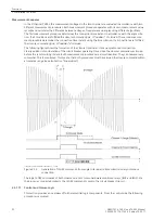
I ue(k) – ue(k–1) I = Δu
max
If the number of faults per cycle are exceeded, the closure command is blocked and an indication issued
(25054
Sync Fail Data
).
This monitoring is only used with configuration as a parallel switching device. This function is not provide for
single-phase synchrocheck applications.
Not shown in
, an additional ADC monitoring is effective for inputs U1 and U2. This monitoring
operates for all connection variants. For this purpose each free fourth analog channel of the ADC is intercon-
nected. For each sampled value of the voltage inputs Ua (corresponds to U1) and Ue (corresponds to U2),
consistency with the original channels is checked for the other ADC.
I ua(k)
ADU1
– ua(k)
ADU2
I ≤ Δu
I ue(k)
ADU1
– ue(k)
ADU2
I ≤ Δu
If the limit is transgressed, the synchronizing function is blocked and at the same time the device is terminated
(live contact is activated), since an error is assumed in the ADCs. An alarm is issued in parallel with this (25036
Error ADC
).
The Phase sequence check detects connection and other faults. It is effective if a multi-phase voltage connec-
tion results (see
) and the parameter 6113
PHASE SEQUENCE
is set to
L1 L2 L3
for a clockwise
phase sequence or
L1 L3 L2
for an anticlockwise phase sequence. If different phase sequences or those
other than the setting are established at inputs U1 and U2, the synchronising function is blocked and corre-
sponding indications are issued (25039
SyncSeq U1 fail
; 25040
SyncSeq U2 fail
). For checking
purposes the phase sequence appears as an operational measured value for both inputs.
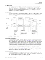
The measurement algorithms and logic functions are in to be found in the displayed measure procedures 1
and 2. Different measurement procedures are used in accordance with the two-channel capability in order to
exclude overfunctioning caused by process conditioned (systematic) errors. In addition other procedures are
effective in the background. The closure monitoring checks the Consistency of both measurement proce-
dures. If both procedures do not result in the closure command within a prescribed period, this causes a rejec-
tion and an indication (
Sync sup. α
) is issued.
Additionally, it is monitored whether both measuring procedures are operating in the same mode (SYNCHRO-
NOUS or ASYNCHRONOUS). If this is not the case, message
Sync sup.asym.
is generated and no close
commands can be issued. Should this condition prevail for one minute, the synchronization is terminated with
the fault message e.g.
Sy1 Error
.
The start input must be activated again for continuation of synchronisation. These monitorings are operative
with two channel mode.
Overfunctionings of Relay triggering are avoided by the two-channel activation of both closure relays. With
this both measurement procedures cross activate the semiconductors. In addition in the background coil acti-
vation is monitored. For this purpose the semiconductors are activated individually and the response is read
back. Both interruptions and a shorted semiconductor are detected. Detected errors result in a blocking of the
device and a corresponding indication (
Error Relay R1
or
Error Relay R2
) is issued.
Furthermore monitoring is supported by a Plausibility settings check as well as by the Number of synchro-
nizing function groups:
•
Check for uniquivocality of the function group (only one in each case may be selected)
•
Check of configuration (mixed configuration single-phase/multi-phase is not permitted)
•
Parametrization check (valid limits)
•
Evaluation of monitoring functions
On absent or multiple selection of synchronizing function group the indication
Sy1 active
drops out. On
synchronisation start in addition the indication
Sync FG-Error
is output.
In the event of configurations errors the indication
Sy1 active
drops out and the indication
Sync
Fail.Conf.
appears.
Furthermore, specific thresholds and settings of the selected function group are checked with regard to para-
metrization. If there is a condition which is not plausible, the indication
Sy1 active
drops out and the indi-
cation
Sy1 ParErr
is output additionally.
If a voltage transformer fault appears at the device via binary inputs (mcb tripping)
>FAIL: VT Ua
to
>FAIL: VT Uf
, likewise synchronization is not started. Note here that of the 6 available binary inputs those
are allocated whose associated voltages Ua to Uf are referred to for synchronization.
Functions
2.2 Paralleling Functions
SIPROTEC 4, 7VE61 and 7VE63, Manual
41
C53000-G1176-C163-3, Edition 10.2017
Summary of Contents for SIPROTEC 4 7VE61
Page 8: ...8 SIPROTEC 4 7VE61 and 7VE63 Manual C53000 G1176 C163 3 Edition 10 2017 ...
Page 24: ...24 SIPROTEC 4 7VE61 and 7VE63 Manual C53000 G1176 C163 3 Edition 10 2017 ...
Page 142: ...142 SIPROTEC 4 7VE61 and 7VE63 Manual C53000 G1176 C163 3 Edition 10 2017 ...
Page 192: ...192 SIPROTEC 4 7VE61 and 7VE63 Manual C53000 G1176 C163 3 Edition 10 2017 ...
Page 222: ...222 SIPROTEC 4 7VE61 and 7VE63 Manual C53000 G1176 C163 3 Edition 10 2017 ...
Page 230: ...230 SIPROTEC 4 7VE61 and 7VE63 Manual C53000 G1176 C163 3 Edition 10 2017 ...
Page 256: ...256 SIPROTEC 4 7VE61 and 7VE63 Manual C53000 G1176 C163 3 Edition 10 2017 ...
Page 314: ...314 SIPROTEC 4 7VE61 and 7VE63 Manual C53000 G1176 C163 3 Edition 10 2017 ...
Page 316: ...316 SIPROTEC 4 7VE61 and 7VE63 Manual C53000 G1176 C163 3 Edition 10 2017 ...
Page 330: ...330 SIPROTEC 4 7VE61 and 7VE63 Manual C53000 G1176 C163 3 Edition 10 2017 ...


