[logik-dead-line-freigabebedingungen-220403-kn, 1, en_GB]
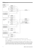
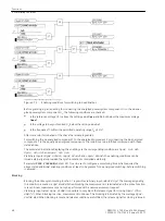
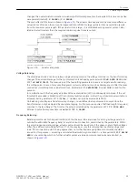
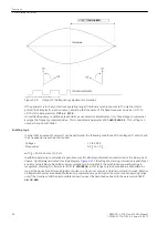
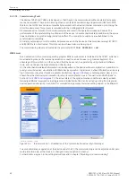
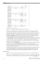
Figure 2-13
Enabling conditions for switching to dead line/bus
Before granting e.g. an enabling for connecting the energized power system component U
1
to the de-ener-
gized power system component U
2
, the following conditions are checked:
•
Is the reference voltage U1 is above the setting value
Umin
and
U>
but below the maximum voltage
Umax
?
•
Is the voltage to be synchronized U
2
below the setting value
U<
?
•
Is the frequency f1 within the permitted operating range f
N
± 3 Hz?
After successful termination of the check the release is granted.
For switching the de-energized component 1 to the energized component 2 or connecting the de-energized
component 1 to the equally de-energized component 2 the conditions to be fulfilled correspond with those
stated above.
The associated indications displaying the enabling via the corresponding condition are
Sync. U1> U2<
,
Sync. U1< U2>
and
Sync. U1< U2<
.
Via binary inputs
>Sync U1>U2<
,
>Sync U1<U2>
and
>Sync U1<U2<
the enabling conditions can be
issued externally also provided the synchronization is controlled externally.
Parameter
TSUP VOLTAGE
(address 6111) can be set to configure a monitoring time which requires the
above stated additional enabling conditions at least to be present for de-energized switching, before switching
is allowed.
Blocking
Blocking the entire synchronizing function 1 is possible via binary input
>BLOCK Sy1
. The message signaling
this condition is made via
Sy1 BLOCK
. When blocking the measurement is terminated and the entire function
is reset. A new measurement can only be performed with a new measurement request.
Via binary input
>BLK Sync CLOSE
it is possible to only block the release signal for closing (
Sync Clos-
eRel 1
). When blocking is active, measurement continues. The blocking is indicated by the message
Sync.
CLOSE BLK
. When blocking is reset and release conditions are fulfilled, the release signal for closing is issued.
Functions
2.2 Paralleling Functions
48
SIPROTEC 4, 7VE61 and 7VE63, Manual
C53000-G1176-C163-3, Edition 10.2017
Summary of Contents for SIPROTEC 4 7VE61
Page 8: ...8 SIPROTEC 4 7VE61 and 7VE63 Manual C53000 G1176 C163 3 Edition 10 2017 ...
Page 24: ...24 SIPROTEC 4 7VE61 and 7VE63 Manual C53000 G1176 C163 3 Edition 10 2017 ...
Page 142: ...142 SIPROTEC 4 7VE61 and 7VE63 Manual C53000 G1176 C163 3 Edition 10 2017 ...
Page 192: ...192 SIPROTEC 4 7VE61 and 7VE63 Manual C53000 G1176 C163 3 Edition 10 2017 ...
Page 222: ...222 SIPROTEC 4 7VE61 and 7VE63 Manual C53000 G1176 C163 3 Edition 10 2017 ...
Page 230: ...230 SIPROTEC 4 7VE61 and 7VE63 Manual C53000 G1176 C163 3 Edition 10 2017 ...
Page 256: ...256 SIPROTEC 4 7VE61 and 7VE63 Manual C53000 G1176 C163 3 Edition 10 2017 ...
Page 314: ...314 SIPROTEC 4 7VE61 and 7VE63 Manual C53000 G1176 C163 3 Edition 10 2017 ...
Page 316: ...316 SIPROTEC 4 7VE61 and 7VE63 Manual C53000 G1176 C163 3 Edition 10 2017 ...
Page 330: ...330 SIPROTEC 4 7VE61 and 7VE63 Manual C53000 G1176 C163 3 Edition 10 2017 ...


