i
i
NOTE
indicates information on the device, handling of the device, or the respective part of the instruction manual
which is important to be noted.
Typographic and Symbol Conventions
The following text formats are used when literal information from the device or to the device appear in the
text flow:
Parameter Names
Designators of configuration or function parameters which may appear word-for-word in the display of the
device or on the screen of a personal computer (with operation software DIGSI), are marked in bold letters in
monospace type style. The same applies to titles of menus.
1234A
Parameter addresses have the same character style as parameter names. Parameter addresses contain the
suffix
A
in the overview tables if the parameter can only be set in DIGSI via the option Display additional
settings.
Parameter Options
Possible settings of text parameters, which may appear word-for-word in the display of the device or on the
screen of a personal computer (with operation software DIGSI), are additionally written in italics. The same
applies to the options of the menus.
Indications
Designators for information, which may be output by the relay or required from other devices or from the
switch gear, are marked in a monospace type style in quotation marks.
Deviations may be permitted in drawings and tables when the type of designator can be obviously derived
from the illustration.
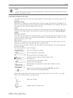
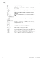
The following symbols are used in drawings:
Device-internal logical input signal
Device-internal logical output signal
Internal input signal of an analog quantity
External binary input signal with number (binary input,
input indication)
External binary output signal with number
(example of a value indication)
External binary output signal with number (device indication) used as
input signal
Example of a parameter switch designated FUNCTION with address
1234 and the possible settings
Ein
and
Aus
Besides these, graphical symbols are used in accordance with IEC 60617-12 and IEC 60617-13 or similar.
Some of the most frequently used are listed below:
Analog input variable
AND-gate operation of input values
Preface
SIPROTEC 4, 7VE61 and 7VE63, Manual
5
C53000-G1176-C163-3, Edition 10.2017
Summary of Contents for SIPROTEC 4 7VE61
Page 8: ...8 SIPROTEC 4 7VE61 and 7VE63 Manual C53000 G1176 C163 3 Edition 10 2017 ...
Page 24: ...24 SIPROTEC 4 7VE61 and 7VE63 Manual C53000 G1176 C163 3 Edition 10 2017 ...
Page 142: ...142 SIPROTEC 4 7VE61 and 7VE63 Manual C53000 G1176 C163 3 Edition 10 2017 ...
Page 192: ...192 SIPROTEC 4 7VE61 and 7VE63 Manual C53000 G1176 C163 3 Edition 10 2017 ...
Page 222: ...222 SIPROTEC 4 7VE61 and 7VE63 Manual C53000 G1176 C163 3 Edition 10 2017 ...
Page 230: ...230 SIPROTEC 4 7VE61 and 7VE63 Manual C53000 G1176 C163 3 Edition 10 2017 ...
Page 256: ...256 SIPROTEC 4 7VE61 and 7VE63 Manual C53000 G1176 C163 3 Edition 10 2017 ...
Page 314: ...314 SIPROTEC 4 7VE61 and 7VE63 Manual C53000 G1176 C163 3 Edition 10 2017 ...
Page 316: ...316 SIPROTEC 4 7VE61 and 7VE63 Manual C53000 G1176 C163 3 Edition 10 2017 ...
Page 330: ...330 SIPROTEC 4 7VE61 and 7VE63 Manual C53000 G1176 C163 3 Edition 10 2017 ...


