[ve6-beruecksichtigung-einer-phasenwinkeldrehung-170403-oz, 1, en_GB]
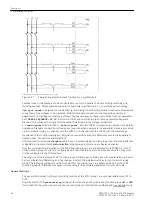
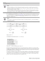
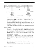
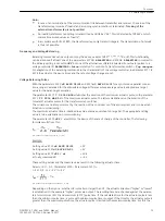
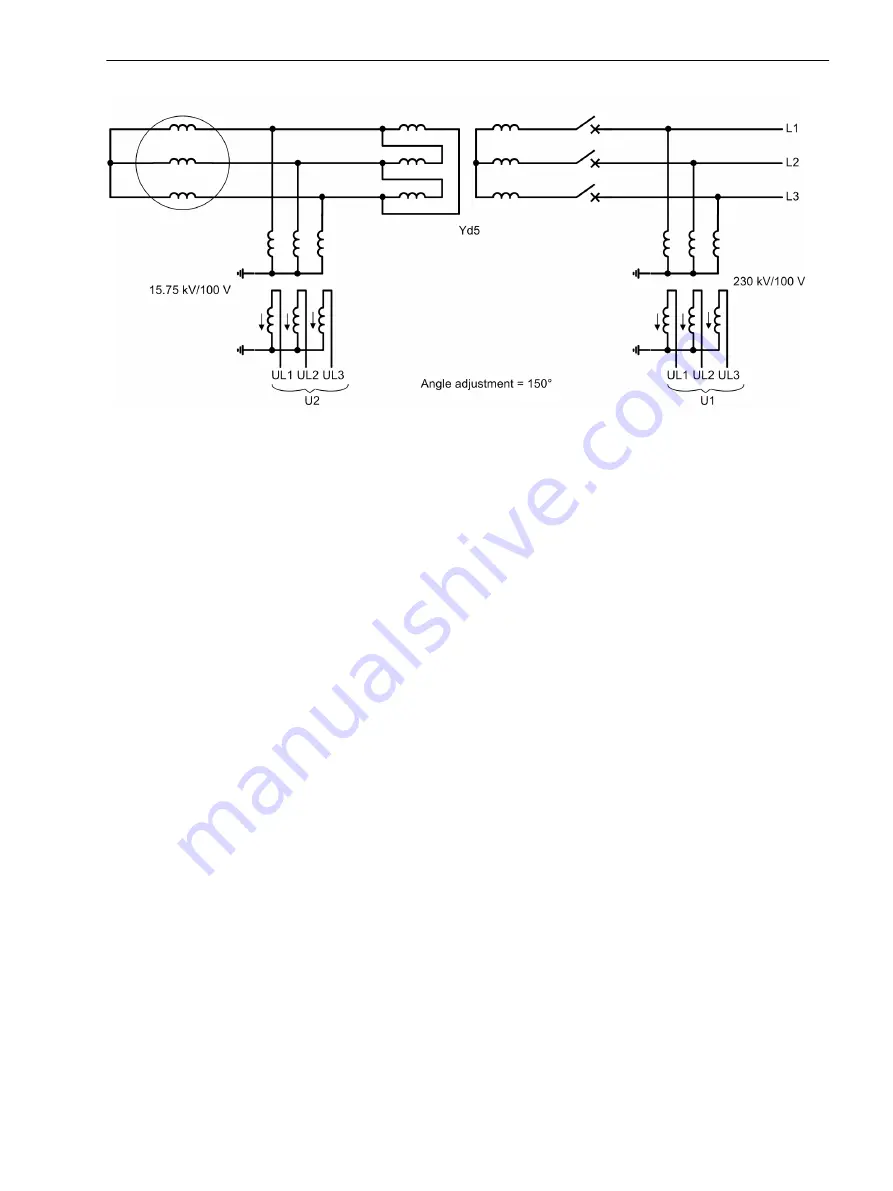
Figure 2-32
Consideration of a phase angle rotation
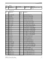
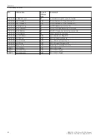
At address 6124
VT Un1, primary
the primary transformer rated voltage of side 1 is entered for correct
primary representation of the measured values. Analog to this the primary transformer rated voltage of side 2
is entered under address 6125
VT Un2, primary
.
Address 6126
Unom SECONDARY
represents the secondary transformer rated voltage.
Under address 6127
T CLS CMD MIN
, sets the duration of the closing command to the circuit breaker. This
must always be greater than the circuit breaker closing time (address 6120); such that the circuit breaker
safely completes the closure and has interrupted closure control circuit with its auxiliary contact. For safety
reasons, the time should not be set longer than necessary.
The default setting of
0.1 s
corresponds to common circuit breakers; however, the particular power system
must be checked.
Asynchronous Conditions
With asynchronous systems a connection command is issued by the synchronizing function so that, taking into
consideration the operating time of the circuit breaker (address 6120
T-CB close
), the power systems are
coupled when the vectors are in phase. Apart from the circuit breaker closing time (make-time) 6120
T-CB
close
6130 to 6133 for this purpose are relevant.
With parameters 6130
dU ASYN U2>U1
(admissible voltage difference, if U2 is greater than U1) and 6131
dU
ASYN U2<U1
(admissible voltage difference if U2 is less than U1) the admissible voltage differences can be
also set asymmetrically.
To prevented the reactive power loading of the generator after connection from becoming too large, a setting
of 2 % of rated voltage has proven suitable.
Parameters 6132
df ASYN f2>f1
(admissible frequency difference if f2 exceeds f1) and 6133
df ASYN
f2<f1
(admissible frequency difference if f2 is less than f1) restrict the operating range for asynchronous
connection. The availability of two parameters enables an asymmetrical release to be set.
A usual setting value is about 0.1 Hz. This keeps the possible active power compensation within limits on
connection.
Synchronous Conditions
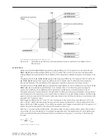
Parameter 6140
SYNC PERMIS.
selects whether on undershooting of the threshold
F SYNCHRON
(see
below) only the synchronism conditions are checked (
YES
) or under all circumstances the breaker operating
time is to be also considered (
NO
).
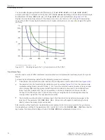
On synchronism of generators this operating mode is to be disabled. The parameter must be at
NO
. On the
other hand a main application is synchronisation of power systems.
Functions
2.2 Paralleling Functions
SIPROTEC 4, 7VE61 and 7VE63, Manual
67
C53000-G1176-C163-3, Edition 10.2017
Summary of Contents for SIPROTEC 4 7VE61
Page 8: ...8 SIPROTEC 4 7VE61 and 7VE63 Manual C53000 G1176 C163 3 Edition 10 2017 ...
Page 24: ...24 SIPROTEC 4 7VE61 and 7VE63 Manual C53000 G1176 C163 3 Edition 10 2017 ...
Page 142: ...142 SIPROTEC 4 7VE61 and 7VE63 Manual C53000 G1176 C163 3 Edition 10 2017 ...
Page 192: ...192 SIPROTEC 4 7VE61 and 7VE63 Manual C53000 G1176 C163 3 Edition 10 2017 ...
Page 222: ...222 SIPROTEC 4 7VE61 and 7VE63 Manual C53000 G1176 C163 3 Edition 10 2017 ...
Page 230: ...230 SIPROTEC 4 7VE61 and 7VE63 Manual C53000 G1176 C163 3 Edition 10 2017 ...
Page 256: ...256 SIPROTEC 4 7VE61 and 7VE63 Manual C53000 G1176 C163 3 Edition 10 2017 ...
Page 314: ...314 SIPROTEC 4 7VE61 and 7VE63 Manual C53000 G1176 C163 3 Edition 10 2017 ...
Page 316: ...316 SIPROTEC 4 7VE61 and 7VE63 Manual C53000 G1176 C163 3 Edition 10 2017 ...
Page 330: ...330 SIPROTEC 4 7VE61 and 7VE63 Manual C53000 G1176 C163 3 Edition 10 2017 ...


