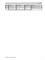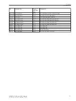
No.
Information
Type of
Informa-
tion
Comments
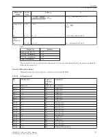
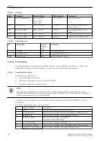
25021
dUmax =
MVT
Voltage difference dU Maximum
25022
dfmin =
MVT
Frequency difference df Minimum
25023
dfmax =
MVT
Frequency difference df Maximum
25024
dαmin =
MVT
Angel difference dalpha Minimum
25025
dαmax =
MVT
Angel difference dalpha Maximum
25027
>f1 MiMa Reset
SP
>f1 MIN/MAX Buffer Reset
25028
>U2 MiMa Reset
SP
>U2 MIN/MAX Buffer Reset
25029
>f2 MiMa Reset
SP
>f2 MIN/MAX Buffer Reset
25030
>dU MiMa Reset
SP
>dU MIN/MAX Buffer Reset
25031
>df MiMa Reset
SP
>df MIN/MAX Buffer Reset
25032
>dα MiMa Reset
SP
>dalpha MIN/MAX Buffer Reset
Limit-Measured Values
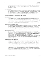
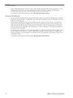
To recognize extraordinary operational conditions, specific warning levels can be programmed. If a preset limit
is overshot or undershot, an indication is generated. This indication can also be allocated to output relays and
LEDs.
The user can thus defining warning levels in accordance with his application, which he can freely logically allo-
cate to measured or average values supplied by the device.
On delivery of the 7VE61 and 7VE63 no limit levels are configured.
Applications
•
The limit values for measured values work with multiple measurement repetitions and lower priority than
the synchronization and the protection functions. For that reason, this limit value detection may not
respond to fast measured value changes before protection functions are started and tripped. Thus this
functionality is not suitable for blocking protection functions. In such cases, threshold supervisions are
suitable (see Section
).
Setting Notes
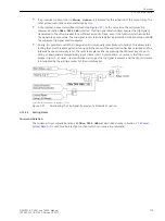
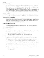
Set Points for Measured Values
Setting is performed in the DIGSI Configuration Matrix under Settings, Masking I/O (Configuration Matrix).
Set the filter "Measured and Metered Values Only" and select the configuration group "Set Points (MV)". Here,
default settings may be changed or new set points defined.
Settings must be applied in percent and usually refer to nominal values of the device.
Statistics
Functional Description
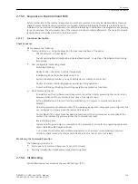
Number of Trips
The number of trips initiated by the 7VE61 and 7VE63 is counted, as long as the position of the circuit breaker
is monitored via breaker auxiliary contacts and binary inputs. To use this function, the internal pulse counter
#of TRIPs=
is masked in the matrix to a binary input that is controlled by the circuit breaker OPEN position.
The pulse metered value
#of TRIPs=
can be found in the
Statistics
group if the option “Measured and
Metered Values Only” was enabled in the configuration matrix.
2.14.5
2.14.5.1
2.14.6
2.14.6.1
Functions
2.14 Auxiliary Functions
SIPROTEC 4, 7VE61 and 7VE63, Manual
125
C53000-G1176-C163-3, Edition 10.2017
Summary of Contents for SIPROTEC 4 7VE61
Page 8: ...8 SIPROTEC 4 7VE61 and 7VE63 Manual C53000 G1176 C163 3 Edition 10 2017 ...
Page 24: ...24 SIPROTEC 4 7VE61 and 7VE63 Manual C53000 G1176 C163 3 Edition 10 2017 ...
Page 142: ...142 SIPROTEC 4 7VE61 and 7VE63 Manual C53000 G1176 C163 3 Edition 10 2017 ...
Page 192: ...192 SIPROTEC 4 7VE61 and 7VE63 Manual C53000 G1176 C163 3 Edition 10 2017 ...
Page 222: ...222 SIPROTEC 4 7VE61 and 7VE63 Manual C53000 G1176 C163 3 Edition 10 2017 ...
Page 230: ...230 SIPROTEC 4 7VE61 and 7VE63 Manual C53000 G1176 C163 3 Edition 10 2017 ...
Page 256: ...256 SIPROTEC 4 7VE61 and 7VE63 Manual C53000 G1176 C163 3 Edition 10 2017 ...
Page 314: ...314 SIPROTEC 4 7VE61 and 7VE63 Manual C53000 G1176 C163 3 Edition 10 2017 ...
Page 316: ...316 SIPROTEC 4 7VE61 and 7VE63 Manual C53000 G1176 C163 3 Edition 10 2017 ...
Page 330: ...330 SIPROTEC 4 7VE61 and 7VE63 Manual C53000 G1176 C163 3 Edition 10 2017 ...

