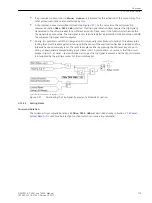
mation is not performed within one minute, the setpoint flashing changes again to the corresponding actual
status. Cancellation via the Enter key is possible at any time before the control command is issued.
During normal processing, the control display indicates the new actual status after the control command was
executed and the message command end appears at the lower display edge. In case of control commands
with feedback, the message FB reached is displayed for a short time before this.
If the attempted command fails, because an interlocking condition is not met, an error message appears in the
display. The message indicates why the control command was not accepted (see also SIPROTEC 4 System
Description). This message must be acknowledged with Enter before any further control commands can be
issued.
Operation using DIGSI
Switchgear devices can be controlled via the operator control interface with a PC using the DIGSI operating
program. The procedure to do so is described in the SIPROTEC 4 System Description (Control of Switchgear).
Operation Using the System Interface
Control of switching devices can be performed via the serial system interface and a connection to the switch-
gear control and protection system. Please check MLFB order number to ensure that your individual relay has a
SCADA interface module that supports this. Furthermore, certain settings for the serial interface in the device
need to be carried out (see SIPROTEC 4 System Description).
Types of Commands
In conjunction with the power system control several command types can be distinguished for the device.
Functional Description
Commands to the System
These are all commands that are directly output to the switchgear to change their process state:
•
Switching commands for the control of circuit breakers (not synchronized), disconnectors and earth elec-
trodes,
•
Step commands, e.g. raising and lowering transformer LTCs
•
Set-point commands with configurable time settings, e.g. to control Petersen coils
Internal / Pseudo Commands
They do not directly operate binary outputs. They serve to initiate internal functions, simulate changes of
state, or to acknowledge changes of state.
•
Manual overriding commands to manually update information on process-dependent objects such as
annunciations and switching states, e.g. if the communication with the process is interrupted. Manually
overridden objects are flagged as such in the information status and can be displayed accordingly.
•
Tagging commands are issued to establish internal settings, e.g. deleting / presetting the switching
authority (remote vs. local), a parameter set changeover, data transmission block to the SCADA interface,
and measured value set-points.
•
Acknowledgment and resetting commands for setting and resetting internal buffers or data states.
•
Information status command to set/reset the additional information "information status" of a process
object, such as:
–
Input blocking
–
Output Blocking
2.15.2
2.15.2.1
Functions
2.15 Command Processing
132
SIPROTEC 4, 7VE61 and 7VE63, Manual
C53000-G1176-C163-3, Edition 10.2017
Summary of Contents for SIPROTEC 4 7VE61
Page 8: ...8 SIPROTEC 4 7VE61 and 7VE63 Manual C53000 G1176 C163 3 Edition 10 2017 ...
Page 24: ...24 SIPROTEC 4 7VE61 and 7VE63 Manual C53000 G1176 C163 3 Edition 10 2017 ...
Page 142: ...142 SIPROTEC 4 7VE61 and 7VE63 Manual C53000 G1176 C163 3 Edition 10 2017 ...
Page 192: ...192 SIPROTEC 4 7VE61 and 7VE63 Manual C53000 G1176 C163 3 Edition 10 2017 ...
Page 222: ...222 SIPROTEC 4 7VE61 and 7VE63 Manual C53000 G1176 C163 3 Edition 10 2017 ...
Page 230: ...230 SIPROTEC 4 7VE61 and 7VE63 Manual C53000 G1176 C163 3 Edition 10 2017 ...
Page 256: ...256 SIPROTEC 4 7VE61 and 7VE63 Manual C53000 G1176 C163 3 Edition 10 2017 ...
Page 314: ...314 SIPROTEC 4 7VE61 and 7VE63 Manual C53000 G1176 C163 3 Edition 10 2017 ...
Page 316: ...316 SIPROTEC 4 7VE61 and 7VE63 Manual C53000 G1176 C163 3 Edition 10 2017 ...
Page 330: ...330 SIPROTEC 4 7VE61 and 7VE63 Manual C53000 G1176 C163 3 Edition 10 2017 ...


