Mounting and Connections
!
WARNING
Warning of improper transport, storage, installation or erection of the device.
Failure to observe these precautions can result in death, personal injury or substantial property
damage.
²
Unproblematic and safe use of this device depends on proper transport, storage, installation and erec-
tion of the device taking into account the warnings and instructions of the device manual.
²
In particular the general installation and safety regulations for working in power current installations
(for example, ANSI, IEC, EN, DIN, or other national and international regulations) must be observed.
Configuration Information
Prerequisites
For mounting and connection the following requirements and conditions must be met:
The rated device data has been tested as recommended in the
and their
compliance with these data is verified with the Power System Data.
Connection Options
General diagrams are shown in Appendix
. Connection examples for voltage trans-
former circuits are provided in
. The configuration of the synchronization function
must be checked to ensure it corresponds with the connections to the device.
Binary Inputs and Outputs
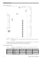
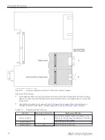
Allocation possibilities of binary inputs and outputs, i.e. the individual matching to the system are described in
the
. The presettings of the device are listed in Appendix
. Check also whether the labelling corresponds to the allocated message func-
tions.
Changing Setting Groups
If binary inputs are used to switch setting groups, please observe the following:
•
Two binary inputs must be dedicated to the purpose of changing setting groups when four groups are to
be switched. One binary input must be set for
>Set Group Bit0
, the other input for
>Set Group
Bit1
. If either of these input functions is not assigned, then it is considered as not controlled.
•
To control two setting groups, one binary input set for
>Set Group Bit0
is sufficient since the binary
input
>Set Group Bit1
, which is not assigned, is considered to be not controlled.
•
The status of the signals controlling the binary inputs to activate a particular setting group must remain
constant as long as that particular group is to remain active.
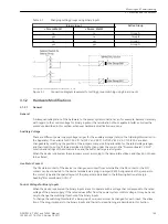
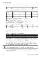
The following table shows the allocation of the binary inputs to the setting groups A to D and a simplified
connection diagram for the two binary inputs is illustrated in the following figure. The figure illustrates an
example in which both Set Group Bits 0 and 1 are configured to be controlled (actuated) when the associated
binary input is energized (high).
Where:
no =
not triggered
yes =
triggered
3.1
3.1.1
Mounting and Commissioning
3.1 Mounting and Connections
144
SIPROTEC 4, 7VE61 and 7VE63, Manual
C53000-G1176-C163-3, Edition 10.2017
Summary of Contents for SIPROTEC 4 7VE61
Page 8: ...8 SIPROTEC 4 7VE61 and 7VE63 Manual C53000 G1176 C163 3 Edition 10 2017 ...
Page 24: ...24 SIPROTEC 4 7VE61 and 7VE63 Manual C53000 G1176 C163 3 Edition 10 2017 ...
Page 142: ...142 SIPROTEC 4 7VE61 and 7VE63 Manual C53000 G1176 C163 3 Edition 10 2017 ...
Page 192: ...192 SIPROTEC 4 7VE61 and 7VE63 Manual C53000 G1176 C163 3 Edition 10 2017 ...
Page 222: ...222 SIPROTEC 4 7VE61 and 7VE63 Manual C53000 G1176 C163 3 Edition 10 2017 ...
Page 230: ...230 SIPROTEC 4 7VE61 and 7VE63 Manual C53000 G1176 C163 3 Edition 10 2017 ...
Page 256: ...256 SIPROTEC 4 7VE61 and 7VE63 Manual C53000 G1176 C163 3 Edition 10 2017 ...
Page 314: ...314 SIPROTEC 4 7VE61 and 7VE63 Manual C53000 G1176 C163 3 Edition 10 2017 ...
Page 316: ...316 SIPROTEC 4 7VE61 and 7VE63 Manual C53000 G1176 C163 3 Edition 10 2017 ...
Page 330: ...330 SIPROTEC 4 7VE61 and 7VE63 Manual C53000 G1176 C163 3 Edition 10 2017 ...

