Test Mode and Transmission Block
If the device is connected to a central or main computer system via the SCADA interface, then the information
that is transmitted can be influenced. This is only possible with some of the protocols available (see Table
“Protocol- dependent functions” in Appendix
D.7 Protocol-dependent Functions
If Test mode is set ON, then a message sent by a SIPROTEC 4 device to the main system has an additional test
bit. This bit allows the message to be recognized as resulting from testing and not an actual fault or power
system event. In addition to this, the user can determine by activating the transmission block that no indica-
tions at all are transferred via the system interface during a test operation.
The SIPROTEC 4 System Manual describes how to activate and deactivate test mode and blocked data trans-
mission. Note that when DIGSI is being used, the program must be in the Online operating mode for the test
features to be used.
Checking System Interfaces
Prefacing Remarks
If the device features a system interface and uses it to communicate with the control centre, the DIGSI device
operation can be used to test if messages are transmitted correctly. This test option should however definitely
“not” be used while the device is in service on a live system.
!
DANGER
Danger evolving from operating the equipment (e.g. circuit breakers, disconnectors) by means of the
test function
Non-observance of the following measure will result in death, severe personal injury or substantial
property damage.
²
Equipment used to allow switching such as circuit breakers or disconnectors is to be checked only
during commissioning. Do not under any circumstances check them by means of the testing mode
during „real“ operation performing transmission and reception of messages via the system interface.
i
i
NOTE
After termination of the system interface test the device will reboot. Thereby, all annunciation buffers are
erased. If required, these buffers should be extracted with DIGSI prior to the test.
The interface test is carried out using DIGSI in the Online operating mode:
•
Open the Online directory by double-clicking; the operating functions for the device appear.
•
Click on Test; the function selection appears in the right half of the screen.
•
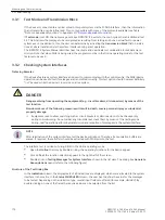
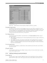
Double-click on Testing Messages for System Interface shown in the list view. The dialog box Generate
Annunciations opens (refer to the following figure).
Structure of the Test Dialog Box
In the Indication column, the display texts of all indications are displayed, which were allocated to the system
interface in the matrix. In the Status SCHEDULED column, the user has to define the value for the messages
to be tested. Depending on the indication type, several input fields are offered (for example,
ON
/
OFF
). By
double-clicking on one of the fields the required value can be selected from the list.
3.3.1
3.3.2
Mounting and Commissioning
3.3 Commissioning
170
SIPROTEC 4, 7VE61 and 7VE63, Manual
C53000-G1176-C163-3, Edition 10.2017
Summary of Contents for SIPROTEC 4 7VE61
Page 8: ...8 SIPROTEC 4 7VE61 and 7VE63 Manual C53000 G1176 C163 3 Edition 10 2017 ...
Page 24: ...24 SIPROTEC 4 7VE61 and 7VE63 Manual C53000 G1176 C163 3 Edition 10 2017 ...
Page 142: ...142 SIPROTEC 4 7VE61 and 7VE63 Manual C53000 G1176 C163 3 Edition 10 2017 ...
Page 192: ...192 SIPROTEC 4 7VE61 and 7VE63 Manual C53000 G1176 C163 3 Edition 10 2017 ...
Page 222: ...222 SIPROTEC 4 7VE61 and 7VE63 Manual C53000 G1176 C163 3 Edition 10 2017 ...
Page 230: ...230 SIPROTEC 4 7VE61 and 7VE63 Manual C53000 G1176 C163 3 Edition 10 2017 ...
Page 256: ...256 SIPROTEC 4 7VE61 and 7VE63 Manual C53000 G1176 C163 3 Edition 10 2017 ...
Page 314: ...314 SIPROTEC 4 7VE61 and 7VE63 Manual C53000 G1176 C163 3 Edition 10 2017 ...
Page 316: ...316 SIPROTEC 4 7VE61 and 7VE63 Manual C53000 G1176 C163 3 Edition 10 2017 ...
Page 330: ...330 SIPROTEC 4 7VE61 and 7VE63 Manual C53000 G1176 C163 3 Edition 10 2017 ...

