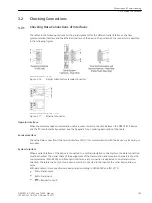
Check in the unexcited condition of the machine with the help of remanent voltages, that all short-circuit
bridges are removed.
Control Circuits
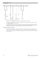
When checking the circuit breaker, the neighbouring isolating switches are opened. It is controlled, that the
circuit breaker itself in position “Manual” of the synchronizing switch (if it exists) can only be closed by
pressing the control discrepancy switch and in position “Automatic” only by 7VE61 and 7VE63.
When using the variants with frequency and voltage balance, the correct reaction of the voltage regulator and
the speed controller on the setpoint commands (higher/lower) is checked from the 7VE61 and 7VE63. In case
of more parallel switching, the before mentioned checking are executed for each synchronizer. Here all
possible questionable circuit breakers are separated at both ends, in order to control the allocation between
the selected synchronizer and the circuit breaker.
Protection Switches for the Voltage Transformers
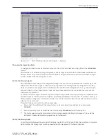
Since it is very important for the undervoltage protection and the synchronization function that these func-
tions are blocked automatically if the circuit breaker for the voltage transformers has tripped, the blocking
should be checked along with the voltage circuits. Each of the 6 voltage inputs of a binary input
>FAIL: VT
Ua
to
>FAIL: VT Uf
can be specified.
Disconnect one voltage transformer miniature circuit breaker of each binary input.
One should check in the Event Log that the VT mcb trip annunciation was detected (e.g
>FAIL: VT Ua
“ON”). A requirement for this is that the auxiliary contact of the VT mcb is connected and correspondingly allo-
cated.
Close the VT mcb again: The above annunciations appear under the "going" operational annunciations, i.e.
with the comment “OFF” (e.g.
>FAIL: VT Ua
“OFF”).
If one of the indications does not appear, check the connection and allocation of these signals.
If the “ON” and “OFF” annunciations are exchanged, then the breaker auxiliary contact type should be checked
and corrected if necessary.
Measured Voltage Circuits, General
The connections of the voltage transformer are tested with primary quantities.
!
WARNING
Warning of dangers evolving from improper primary tests
Non–observance of the following measure can result in death, personal injury or substantial property
damage.
²
Primary test may only be carried out by qualified personnel, who are familiar with the commissioning
of the synchronizing device and protection systems, the operation of the plant and the safety rules
and regulations (switching, earthing, etc.).
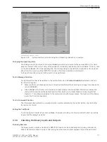
With proper connections of the measuring circuits, none of the measured-values supervision elements should
pick up in the device. If an element detects a problem, the causes which provoked it may be viewed in the
Event Log.
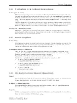
The frequency protection function is verified by a plausibility check of the instantaneous machine speed and
the operational measured value indicated.
The absolute value and the phase sequence of the connected values have to be controlled. The voltages and
the phase sequence voltage can be read on the display in the front display panel, or called up via a PC, and
compared with the actual measured quantities. If the measured quantities are not plausible, the connections
must be checked and revised after switching off the line. The measurements must then be repeated.
Mounting and Commissioning
3.3 Commissioning
176
SIPROTEC 4, 7VE61 and 7VE63, Manual
C53000-G1176-C163-3, Edition 10.2017
Summary of Contents for SIPROTEC 4 7VE61
Page 8: ...8 SIPROTEC 4 7VE61 and 7VE63 Manual C53000 G1176 C163 3 Edition 10 2017 ...
Page 24: ...24 SIPROTEC 4 7VE61 and 7VE63 Manual C53000 G1176 C163 3 Edition 10 2017 ...
Page 142: ...142 SIPROTEC 4 7VE61 and 7VE63 Manual C53000 G1176 C163 3 Edition 10 2017 ...
Page 192: ...192 SIPROTEC 4 7VE61 and 7VE63 Manual C53000 G1176 C163 3 Edition 10 2017 ...
Page 222: ...222 SIPROTEC 4 7VE61 and 7VE63 Manual C53000 G1176 C163 3 Edition 10 2017 ...
Page 230: ...230 SIPROTEC 4 7VE61 and 7VE63 Manual C53000 G1176 C163 3 Edition 10 2017 ...
Page 256: ...256 SIPROTEC 4 7VE61 and 7VE63 Manual C53000 G1176 C163 3 Edition 10 2017 ...
Page 314: ...314 SIPROTEC 4 7VE61 and 7VE63 Manual C53000 G1176 C163 3 Edition 10 2017 ...
Page 316: ...316 SIPROTEC 4 7VE61 and 7VE63 Manual C53000 G1176 C163 3 Edition 10 2017 ...
Page 330: ...330 SIPROTEC 4 7VE61 and 7VE63 Manual C53000 G1176 C163 3 Edition 10 2017 ...


