Setting Notes
Interface selection
No settings are required for operation of the Ethernet system interface module (IEC 61850 Ethernet EN100-
Modul). If the device is equipped with such a module (see MLFB), the module is automatically configured to
the interface available for it.
Information List
No.
Information
Type of
Informa-
tion
Comments
009.0100 Failure Modul
IntSP
Failure EN100 Modul
009.0101 Fail Ch1
IntSP
Failure EN100 Link Channel 1 (Ch1)
009.0102 Fail Ch2
IntSP
Failure EN100 Link Channel 2 (Ch2)
Functional Scope
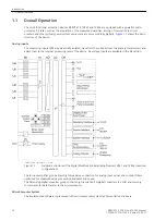
The devices 7VE61 and 7VE63 can have depending on the order variant except for the synchronization func-
tion over numerous protective and additional functions. The hardware and firmware is designed for this scope
of functions.
Also individual functions can be enabled or disabled during configuration. Functions not needed can be thus
be deactivated.
The available protection and synchronizing functions must be configured as
Enabled
or
Disabled
. For indi-
vidual functions a choice between several alternatives is possible, as described below.
Functions that are configured as disabled are not processed by the 7VE61 and 7VE63: There are no indica-
tions, and corresponding settings (functions, limit values) are not queried during configuration.
Functional Description
Setting of the Functional Scope
Configuration settings can be entered using a PC and the software program DIGSI and transferred via the front
operator interface or the rear service interface. The procedure is described in detail in the
.
Entry of password No. 7 (for parameter set) is required to modify configuration settings. Without the pass-
word, the settings may be read, but may not be modified and transmitted to the device.
The functional scope with the available alternatives is set in the Device Configuration dialog box to match
equipment requirements.
i
i
NOTE
Available functions and default settings depend on the device variant ordered (see Appendix
for details). Also, not all combinations of protective functions are possible
because of certain restrictions imposed by the hardware (see Section
Setting Notes
Special Cases
Most settings are self-explanatory. The special cases are described below.
If the setting group change function has to be used, address 103
Grp Chge OPTION
must be set to
Enabled
. In service, simple and fast change, over between up to four different groups of settings is possible.
Only one setting group may be selected and used if this option is
Disabled
.
2.1.2.2
2.1.2.3
2.1.3
2.1.3.1
2.1.3.2
Functions
2.1 General
SIPROTEC 4, 7VE61 and 7VE63, Manual
29
C53000-G1176-C163-3, Edition 10.2017
Summary of Contents for SIPROTEC 4 7VE61
Page 8: ...8 SIPROTEC 4 7VE61 and 7VE63 Manual C53000 G1176 C163 3 Edition 10 2017 ...
Page 24: ...24 SIPROTEC 4 7VE61 and 7VE63 Manual C53000 G1176 C163 3 Edition 10 2017 ...
Page 142: ...142 SIPROTEC 4 7VE61 and 7VE63 Manual C53000 G1176 C163 3 Edition 10 2017 ...
Page 192: ...192 SIPROTEC 4 7VE61 and 7VE63 Manual C53000 G1176 C163 3 Edition 10 2017 ...
Page 222: ...222 SIPROTEC 4 7VE61 and 7VE63 Manual C53000 G1176 C163 3 Edition 10 2017 ...
Page 230: ...230 SIPROTEC 4 7VE61 and 7VE63 Manual C53000 G1176 C163 3 Edition 10 2017 ...
Page 256: ...256 SIPROTEC 4 7VE61 and 7VE63 Manual C53000 G1176 C163 3 Edition 10 2017 ...
Page 314: ...314 SIPROTEC 4 7VE61 and 7VE63 Manual C53000 G1176 C163 3 Edition 10 2017 ...
Page 316: ...316 SIPROTEC 4 7VE61 and 7VE63 Manual C53000 G1176 C163 3 Edition 10 2017 ...
Page 330: ...330 SIPROTEC 4 7VE61 and 7VE63 Manual C53000 G1176 C163 3 Edition 10 2017 ...

