Undervoltage Protection
Undervoltage protection detects voltage dips in electrical machines and devices and avoids inadmissible oper-
ating states and possible loss of stability. In order to achieve all applications, a selected voltage is pulled over
to one of the 6 voltage transformers for the undervoltage protection.
The undervoltage protection together with the overvoltage protection, the vector jump relay, the frequency
change protection and the frequency protection forms a criterion for the network decoupling.
Functional Description
Undervoltage protection consists of two stages. A pickup is signalled as soon as selectable voltage thresholds
are undershot. A trip signal is transmitted if a voltage pickup exists for a selectable time.
In order to ensure that the protection does not accidentally pick up due to a secondary voltage failure, each
stage can be blocked individually or both stages together, via binary input(s), e.g. using a voltage transformer
mcb.
The protection is active via a wide frequency range. The full sensitivity is ensured in the range in which the
frequency response is corrected (0.5 · f
N
to 1.5 · f
N
). The input signal is attenuated outside this frequency
correction range in such way that the undervoltage protection as well as the sensitive tend to overreact.
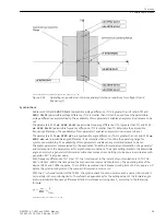
The following figure shows the logic diagram for undervoltage protection.
[ve6-logikdia-unterspannungsschutz-060603-kn, 1, en_GB]
Figure 2-40
Logic Diagram of the Undervoltage Protection
Setting Notes
General
The undervoltage protection is only effective and available if this function was set during protective function
configuration (Section
UNDERVOLTAGE
is set to
Enabled
). If the func-
tion is not required
Disabled
is set. Address 4001
UNDERVOLTAGE
serves to switch the function
ON
or
OFF
or to block only the trip command (
Block relay
).
Setting Values
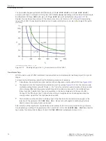
Using the parameter 4007
MEAS. INPUT
one of the 6 voltage inputs (
Ua
to
Uf
) is allocated to the over-
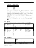
voltage protection. The following allocation applies between voltage input and device connections:
2.4
2.4.1
2.4.2
Functions
2.4 Undervoltage Protection
82
SIPROTEC 4, 7VE61 and 7VE63, Manual
C53000-G1176-C163-3, Edition 10.2017
Summary of Contents for SIPROTEC 4 7VE61
Page 8: ...8 SIPROTEC 4 7VE61 and 7VE63 Manual C53000 G1176 C163 3 Edition 10 2017 ...
Page 24: ...24 SIPROTEC 4 7VE61 and 7VE63 Manual C53000 G1176 C163 3 Edition 10 2017 ...
Page 142: ...142 SIPROTEC 4 7VE61 and 7VE63 Manual C53000 G1176 C163 3 Edition 10 2017 ...
Page 192: ...192 SIPROTEC 4 7VE61 and 7VE63 Manual C53000 G1176 C163 3 Edition 10 2017 ...
Page 222: ...222 SIPROTEC 4 7VE61 and 7VE63 Manual C53000 G1176 C163 3 Edition 10 2017 ...
Page 230: ...230 SIPROTEC 4 7VE61 and 7VE63 Manual C53000 G1176 C163 3 Edition 10 2017 ...
Page 256: ...256 SIPROTEC 4 7VE61 and 7VE63 Manual C53000 G1176 C163 3 Edition 10 2017 ...
Page 314: ...314 SIPROTEC 4 7VE61 and 7VE63 Manual C53000 G1176 C163 3 Edition 10 2017 ...
Page 316: ...316 SIPROTEC 4 7VE61 and 7VE63 Manual C53000 G1176 C163 3 Edition 10 2017 ...
Page 330: ...330 SIPROTEC 4 7VE61 and 7VE63 Manual C53000 G1176 C163 3 Edition 10 2017 ...


