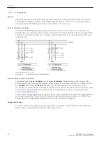
Microcomputer System
Apart from processing the measured values, the microcomputer system µC also executes the actual protection
and control functions. This especially includes:
•
Filtering and conditioning of the measured signals
•
Continuous monitoring of the measured quantities
•
Monitoring of the pickup conditions for the individual protection functions
•
Monitoring of limit values and time sequences
•
Control of signals for logical functions
•
Reaching trip and close command decisions
•
Recording of messages, fault data and fault values for analysis
•
Administration of the operating system and its functions, e.g. data storage, realtime clock, communica-
tion, interfaces, etc.
The information is provided via output amplifier OA.
Binary Inputs and Outputs
Binary inputs from and outputs to the computer system are routed via the I/O modules (inputs and outputs).
The computer system obtains information from the system (e.g remote resetting) or from the external equip-
ment (e.g. blocking commands). Outputs are commands that are issued to the switching devices and
messages for remote signaling of important events and states.
Front Elements
LEDs and an LC display provide information on the function of the device and indicate events, states and
measured values.
Integrated control and numeric keys in conjunction with the LCD facilitate local communication with the
device. Thus, all information of the device, e.g. configuration and setting parameters, operating and fault
messages, and measured values can be retrieved or changed (see also chapter 2 and SIPROTEC 4 System
Description).
Serial Interfaces
The serial operator interface in the front cover enables communication with a personal computer when using
the DIGSI operating program. This allows all device functions to be handled conveniently.
The serial service interface can also be used for communication with a personal computer using DIGSI. This
port is especially well suited for a permanent connection of the devices to the PC or for operation via a
modem.
All device data can be transmitted to a control center through the serial system interface. Various protocols
and physical arrangements are available for this interface to suit a particular application.
An additional interface is provided for time synchronization of the internal clock through external synchroniza-
tion sources.
Further communication protocols can be realized via additional interface modules.
Power Supply
The functional units described are powered by a power supply, PS, with adequate power in the different
voltage levels. Brief supply voltage dips which may occur during short circuits in the auxiliary voltage supply of
the substation, are usually bridged by a capacitor (see also Technical Data, Section
Introduction
1.1 Overall Operation
SIPROTEC 4, 7VK61, Manual
19
C53000-G1176-C159-5, Edition 05.2018
Summary of Contents for SIPROTEC 4 7VK61
Page 8: ...8 SIPROTEC 4 7VK61 Manual C53000 G1176 C159 5 Edition 05 2018 ...
Page 10: ...10 SIPROTEC 4 7VK61 Manual C53000 G1176 C159 5 Edition 05 2018 ...
Page 16: ...16 SIPROTEC 4 7VK61 Manual C53000 G1176 C159 5 Edition 05 2018 ...
Page 176: ...176 SIPROTEC 4 7VK61 Manual C53000 G1176 C159 5 Edition 05 2018 ...
Page 224: ...224 SIPROTEC 4 7VK61 Manual C53000 G1176 C159 5 Edition 05 2018 ...
Page 264: ...264 SIPROTEC 4 7VK61 Manual C53000 G1176 C159 5 Edition 05 2018 ...
Page 270: ...270 SIPROTEC 4 7VK61 Manual C53000 G1176 C159 5 Edition 05 2018 ...
Page 276: ...276 SIPROTEC 4 7VK61 Manual C53000 G1176 C159 5 Edition 05 2018 ...
Page 346: ...346 SIPROTEC 4 7VK61 Manual C53000 G1176 C159 5 Edition 05 2018 ...


