Changing the operating state
On clicking one of the buttons in the column Action you will be prompted for the password No. 6 (for hard-
ware test menus). After correct entry of the password, individual annunciations can be initiated. To do so, click
on the button Send in the corresponding line. The corresponding message is issued and can be read out either
from the event log of the SIPROTEC4 device or from the substation control center.
Further tests remain enabled until the dialog box is closed.
Test in Indication Direction
For all information that is transmitted to the central station, test in Setpoint the desired options in the list
which appears:
•
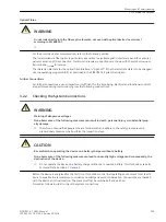
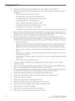
Make sure that each checking process is carried out carefully without causing any danger (see above and
refer to DANGER!)
•
Click on Send and check whether the transmitted information reaches the control centre and shows the
desired reaction. Data which are normally linked via binary inputs (first character “>”) are likewise indi-
cated to the control centre with this procedure. The function of the actual binary inputs is tested sepa-
rately.
Exiting the Procedure
To end the System Interface Test, click on Close. The dialog box closes. The processor system is restarted, then
the device is ready for operation.
Test in Command Direction
Data which are normally linked via binary inputs (first character “>”) are likewise checked with this procedure.
The information transmitted in command direction must be indicated by the central station. Check whether
the reaction is correct.
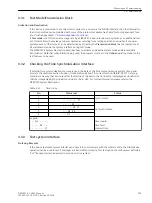
Checking the switching states of the binary Inputs/Outputs
Prefacing Remarks
The binary inputs, outputs, and LEDs of a SIPROTEC 4 device can be individually and precisely controlled in
DIGSI. This feature is used to verify control wiring from the device to plant equipment (operational checks)
during commissioning. This test option should however definitely “not”“ be used while the device is in service
on a live system.
!
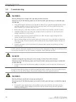
DANGER
A changing of switching states by means of the test function causes a real change of the operating
state at the SIPROTEC 4 device. Connected operating equipment such as circuit breakers or discon-
nectors will be switched in this way!
Non-observance of the following measure will result in death, severe personal injury or substantial
property damage.
²
Equipment used to allow switching such as circuit breakers or disconnectors is to be checked only
during commissioning. Do not under any circumstances check them by means of the testing mode
during “real” operation performing transmission and reception of messages via the system interface.
i
i
NOTE
After termination of the hardware test the device will reboot. Thereby, all annunciation buffers are erased.
If required, these buffers should be extracted with DIGSI prior to the test.
The hardware test can be carried out using DIGSI in the Online operating mode:
3.3.4
Mounting and Commissioning
3.3 Commissioning
SIPROTEC 4, 7VK61, Manual
211
C53000-G1176-C159-5, Edition 05.2018
Summary of Contents for SIPROTEC 4 7VK61
Page 8: ...8 SIPROTEC 4 7VK61 Manual C53000 G1176 C159 5 Edition 05 2018 ...
Page 10: ...10 SIPROTEC 4 7VK61 Manual C53000 G1176 C159 5 Edition 05 2018 ...
Page 16: ...16 SIPROTEC 4 7VK61 Manual C53000 G1176 C159 5 Edition 05 2018 ...
Page 176: ...176 SIPROTEC 4 7VK61 Manual C53000 G1176 C159 5 Edition 05 2018 ...
Page 224: ...224 SIPROTEC 4 7VK61 Manual C53000 G1176 C159 5 Edition 05 2018 ...
Page 264: ...264 SIPROTEC 4 7VK61 Manual C53000 G1176 C159 5 Edition 05 2018 ...
Page 270: ...270 SIPROTEC 4 7VK61 Manual C53000 G1176 C159 5 Edition 05 2018 ...
Page 276: ...276 SIPROTEC 4 7VK61 Manual C53000 G1176 C159 5 Edition 05 2018 ...
Page 346: ...346 SIPROTEC 4 7VK61 Manual C53000 G1176 C159 5 Edition 05 2018 ...


