•
Via binary input (No.2906
>Sync. Start AR
) initiate the measuring request. The synchronism check
must release closing (message
Sync. release
, No. 2951). If not, check all voltage connections and
the corresponding parameters again carefully as described in Section
•
Open the VT mcb of the measuring pointU
sy1
(No. 361
>FAIL:Feeder VT
).
•
Via binary input (No. 2906
>Sync. Start AR
) initiate the measuring request. No close release is given.
•
Reclose the VT mcb of the measuring point U
sy1
wieder einschalten.
Addresses 3515 to 3519must be restored as they were changed for the test. If the allocation of the LEDs or
signal relays was changed for the test, this must also be restored.
Polarity Check for the Current Input
Ι
4
If the standard connection of the device is used whereby current input
Ι
4
is connected in the starpoint of the
set of current transformers (refer also to the connection circuit diagram in the Appendix
), then the correct polarity of the earth current path in general automatically results.
If, however, the current
Ι
4
is supplied by a separate summation CT, an additional direction check for this
current is necessary.
Apart from that the test is carried out with a disconnected trip circuit and primary load current. It must be
noted that during all simulations not exactly corresponding with cases that occur in practice, the asymmetry of
measured values may cause the measured value monitoring to pick up. They must therefore be ignored during
such tests.
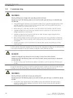
!
DANGER
Hazardous voltages during interruptions in secondary circuits of current transformers
Non-observance of the following measure will result in death, severe personal injury or substantial
property damage.
²
Short-circuit the current transformer secondary circuits before current connections to the device are
opened.
i
i
NOTE
If parameters were changed for this test, they must be returned to their original state after completion of
the test!
Measuring the Operating Time of the Circuit Breaker
Only for Synchronism Check
If the device is equipped with the function for synchronism and voltage check and it is applied, it is necessary -
under asynchronous system conditions - that the operating time of the circuit breaker is measured and set
correctly when closing. If the synchronism check function is not used or only for closing under synchronous
system conditions, this section is irrelevant.
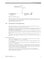
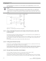
For measuring the operating time a setup as shown in
is recommended. The timer is set to a range
of 1 s and a graduation of 1 ms.
The circuit breaker is closed manually. At the same time the timer is started. After closing the circuit breaker
poles the voltage U
sy1
or U
sy2
appears and the timer is stopped. The time displayed by the timer is the real
circuit breaker closing time.
If the timer is not stopped due to an unfavourable closing moment, the attempt will be repeated.
It is particularly favourable to calculate the mean value from several (3 to 5) successful switching attempts.
3.3.9
3.3.10
Mounting and Commissioning
3.3 Commissioning
SIPROTEC 4, 7VK61, Manual
219
C53000-G1176-C159-5, Edition 05.2018
Summary of Contents for SIPROTEC 4 7VK61
Page 8: ...8 SIPROTEC 4 7VK61 Manual C53000 G1176 C159 5 Edition 05 2018 ...
Page 10: ...10 SIPROTEC 4 7VK61 Manual C53000 G1176 C159 5 Edition 05 2018 ...
Page 16: ...16 SIPROTEC 4 7VK61 Manual C53000 G1176 C159 5 Edition 05 2018 ...
Page 176: ...176 SIPROTEC 4 7VK61 Manual C53000 G1176 C159 5 Edition 05 2018 ...
Page 224: ...224 SIPROTEC 4 7VK61 Manual C53000 G1176 C159 5 Edition 05 2018 ...
Page 264: ...264 SIPROTEC 4 7VK61 Manual C53000 G1176 C159 5 Edition 05 2018 ...
Page 270: ...270 SIPROTEC 4 7VK61 Manual C53000 G1176 C159 5 Edition 05 2018 ...
Page 276: ...276 SIPROTEC 4 7VK61 Manual C53000 G1176 C159 5 Edition 05 2018 ...
Page 346: ...346 SIPROTEC 4 7VK61 Manual C53000 G1176 C159 5 Edition 05 2018 ...

