[funktionsschema-lvs-lshiko-wlk-010802, 1, en_GB]
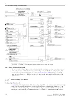
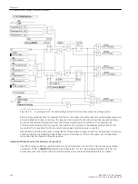
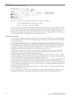
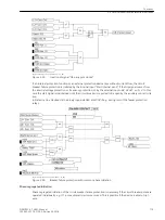
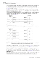
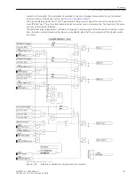
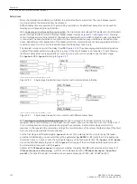
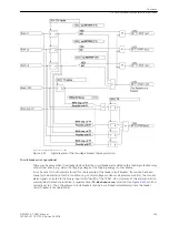
Figure 2-32
Simplified function diagram of circuit breaker failure protection controlled by circuit breaker
auxiliary contact
Current flow monitoring
Each of the phase currents and an additional plausibility current (see below) are filtered by numerical filter
algorithms so that only the fundamental component is used for further evaluation.
Special features recognize the instant of current interruption. In case of sinusoidal currents the current inter-
ruption is detected after approximately a
3
/
4
cycle. With aperiodic DC current components in the fault current
and/or in the current transformer secondary circuit after interruption (e.g. current transformers with linearized
core), or saturation of the current transformers caused by the DC component in the fault current, it can take
up to 1
1
/
4
AC cycles before the interruption of the primary current is reliably detected.
The currents are monitored and compared with the set limit value. Besides the three phase currents, two
further current thresholds are provided in order to allow a plausibility check. If configured correspondingly, a
separate threshold value can be used for this plausibility check (see
).
The earth current
Ι
E
(3·
Ι
0
) is preferably used as plausibility current. The earth current from the starpoint of the
current transformer set will be used if it is connected to the device. If this current is not available, the device
will calculate it from the phase currents using this formula:
3·
Ι
0
=
Ι
L1
+
Ι
L2
+
Ι
L3
Additionally, the value calculated by 7VK61 of three times the negative sequence current 3·
Ι
2
is used for plau-
sibility check. This is calculated according to the equation:
3·
Ι
2
=
Ι
L1
+ a
2
·
Ι
L2
+ a·
Ι
L3
mit
a = e
j120°.
These plausibility currents do not have any direct influence on the basic functionality of the circuit breaker
failure protection but they allow a plausibility check in that at least two current thresholds must have been
exceeded before any of the circuit breaker failure delay times can be started, thus providing high security
against false operation.
In case of high-resistance earth faults it may occur that the earth current exceeds the sensitively parameter-
ized threshold value
3I0> BF
(address 3912), the phase current involved in the short-circuit, however, does
not exceed the threshold value
I> BF
(address 3902).The plausibility monitoring would prevent the breaker
failure protection from being initiated. In this case the pickup threshold of the phase current monitoring
I>
BF
can be switched over to the threshold value
3I0> BF
. For this purpose, use the binary input 1404
>BFac-
tivate3I0>
. This binary input is linked to an external signal which indicates a high resistance fault, e.g.
earth fault detection, or detection of displacement voltage. With this method, the more sensitively parameter-
ized earth current threshold is also used for the phase current monitoring (
).
Functions
2.6 Circuit breaker failure protection (optional)
116
SIPROTEC 4, 7VK61, Manual
C53000-G1176-C159-5, Edition 05.2018
Summary of Contents for SIPROTEC 4 7VK61
Page 8: ...8 SIPROTEC 4 7VK61 Manual C53000 G1176 C159 5 Edition 05 2018 ...
Page 10: ...10 SIPROTEC 4 7VK61 Manual C53000 G1176 C159 5 Edition 05 2018 ...
Page 16: ...16 SIPROTEC 4 7VK61 Manual C53000 G1176 C159 5 Edition 05 2018 ...
Page 176: ...176 SIPROTEC 4 7VK61 Manual C53000 G1176 C159 5 Edition 05 2018 ...
Page 224: ...224 SIPROTEC 4 7VK61 Manual C53000 G1176 C159 5 Edition 05 2018 ...
Page 264: ...264 SIPROTEC 4 7VK61 Manual C53000 G1176 C159 5 Edition 05 2018 ...
Page 270: ...270 SIPROTEC 4 7VK61 Manual C53000 G1176 C159 5 Edition 05 2018 ...
Page 276: ...276 SIPROTEC 4 7VK61 Manual C53000 G1176 C159 5 Edition 05 2018 ...
Page 346: ...346 SIPROTEC 4 7VK61 Manual C53000 G1176 C159 5 Edition 05 2018 ...

