General line data
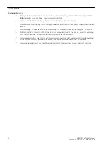
The directional values (power, power factor, work and related min., max., mean and setpoint values), calcu-
lated in the operational measured values, are usually defined with positive direction towards the protected
object. This requires that the connection polarity for the entire device was configured accordingly in the Power
System Data 1 (compare also “Polarity of Current Transformers”, address 201). But it is also possible to reverse
the direction for the outputs without having to change the transformer connections e.g. so that the active
power flow from the line to the busbar is indicated in the positive sense. Set under the address 1107
P,Q
sign
the option
reversed
. If the setting is
not reversed
(default), the positive direction for energy flow
from busbar to line are evaluated as being positive.
Circuit breaker status
Information regarding the circuit breaker position is required by various protection and supplementary func-
tions to ensure their optimal functionality. The device has a circuit breaker status recognition which processes
the status of the circuit breaker auxiliary contacts and contains also a detection based on the measured
currents and voltages for opening and closing (see also Section
In address 1130 the residual current
PoleOpenCurrent
is set, which will definitely not be exceeded when
the circuit breaker pole is open. If parasitic currents (e.g. through induction) can be excluded when the circuit
breaker is open, this setting may be very sensitive. Otherwise this setting must be increased. Usually the
presetting is sufficient. This parameter can only be altered in DIGSI at Display Additional Settings.
The residual voltage
PoleOpenVoltage
, which will definitely not be exceeded when the circuit breaker pole
is open, is set in address 1131. Voltage transformers must be on the line side. The setting should not be too
sensitive because of possible parasitic voltages (e.g. due to capacitive coupling). It must in any event be set
below the smallest phase-earth voltage which may be expected during normal operation. Usually the preset-
ting is sufficient. This parameter can only be altered in DIGSI at Display Additional Settings.
Address 1135
Reset Trip CMD
determines under which conditions a trip command is reset. If
CurrentO-
penPole
is set, the trip command is reset as soon as the current disappears. It is important that the value set
in address 1130
PoleOpenCurrent
(see above) is undershot. If
Current AND CB
is set, the circuit breaker
auxiliary contact must send a message that the circuit breaker is open. It is a prerequisite for this setting that
the position of the auxiliary contacts is allocated via a binary input.
For special applications, in which the device trip command does not always lead to a complete cutoff of the
current, the setting
Pickup Reset
can be chosen. In this case, the trip command is reset as soon as the
pickup of the tripping protection function drops off and - just as with the other setting options- the minimum
trip command duration (address 240) has elapsed. The setting
Pickup Reset
makes sense, for instance,
during the test of the protection equipment, when the system-side load current cannot be cut off and the test
current is injected in parallel to the load current.
i
i
NOTE
For CB Test and automatic reclosure the CB auxiliary contact status derived with the binary inputs >CB1 ...
(No. 366 to 371, 410 and 411) is relevant to indicate the CB switching status. The other binary inputs
>CB ... (No. 351 to 353, 379 and 380) are used for detecting the status of the line (address 1134) and for
reset of the trip command (address 1135). Address 1135 is also used by other protection functions, e.g. by
the echo function, energization in case of overcurrent etc. For use with one circuit breaker only, both
binary input functions, e.g. 366 and 351, can be allocated to the same physical input. For applications with
2 circuit breakers per feeder (1.5 circuit breaker systems or ring bus), the binary inputs >CB1... must be
connected to the correct circuit breaker. The binary inputs >CB... then need the correct signals for detecting
the line status. In certain cases, an additional CFC logic may be necessary.
Address 1136
OpenPoleDetect.
defines the criteria for operating the internal open-pole detector (see also
, Subsection Open-Pole Detector). When using the default setting
w/ meas-
urement
, all available data are evaluated that indicate single-pole dead time. The internal trip command and
pickup indications, the current and voltage measured values and the CB auxiliary contacts are used. To eval-
uate only the auxiliary contacts including the phase currents, set the address 1136 to
Current AND CB
. If
you do not wish to detect single-pole dead time, set
OpenPoleDetect.
to
OFF
.
For manual closure of the circuit breaker via binary inputs, it can be specified in address 1151
MAN. CLOSE
whether the integrated manual CLOSE detection checks the synchronism between the busbar voltage and the
Functions
2.1 General
38
SIPROTEC 4, 7VK61, Manual
C53000-G1176-C159-5, Edition 05.2018
Summary of Contents for SIPROTEC 4 7VK61
Page 8: ...8 SIPROTEC 4 7VK61 Manual C53000 G1176 C159 5 Edition 05 2018 ...
Page 10: ...10 SIPROTEC 4 7VK61 Manual C53000 G1176 C159 5 Edition 05 2018 ...
Page 16: ...16 SIPROTEC 4 7VK61 Manual C53000 G1176 C159 5 Edition 05 2018 ...
Page 176: ...176 SIPROTEC 4 7VK61 Manual C53000 G1176 C159 5 Edition 05 2018 ...
Page 224: ...224 SIPROTEC 4 7VK61 Manual C53000 G1176 C159 5 Edition 05 2018 ...
Page 264: ...264 SIPROTEC 4 7VK61 Manual C53000 G1176 C159 5 Edition 05 2018 ...
Page 270: ...270 SIPROTEC 4 7VK61 Manual C53000 G1176 C159 5 Edition 05 2018 ...
Page 276: ...276 SIPROTEC 4 7VK61 Manual C53000 G1176 C159 5 Edition 05 2018 ...
Page 346: ...346 SIPROTEC 4 7VK61 Manual C53000 G1176 C159 5 Edition 05 2018 ...

