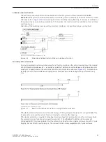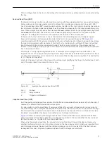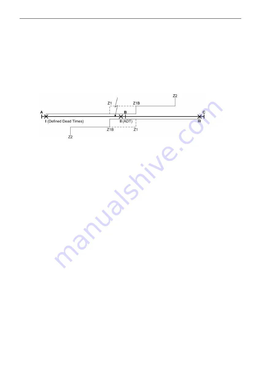
In the illustrated example, the lines are disconnected at positions I, II and III. In I reclosure takes place after the
configured dead time. At position III a reduced dead time can be used (see above) if there is also an infeed on
busbar B.
If the fault has been cleared (successful reclosure), line A - B is re-connected to the voltage at busbar A
through position I. Device II detects this voltage and also recloses after a short delay (to ensure a sufficient
voltage measuring time). The fault is cleared.
If the fault has not been cleared after reclosure at I (unsuccessful reclosure), the line will be disconnected
again in position I with the result that no healthy voltage is detected at location II so that the circuit breaker
there does not reclose.
In the case of multiple reclosure the sequence may be repeated several times following an unsuccessful reclo-
sure until one of the reclosure attempts is successful or a final trip takes place.
[beispiel-asp-wlk-310702, 1, en_GB]
Figure 2-9
Example of adaptive dead time (ADT)
A, B, C
Busbars
I, II, III
Relay locations
X
Tripped circuit breakers
As is shown by the example, the adaptive dead time has the following advantages:
•
The circuit breaker at position II is not reclosed if the fault persists and is not unnecessarily stressed as a
result.
•
With non-selective tripping by overreach at position III no further trip and reclose cycles occur here
because the short-circuit path via busbar B and position II remains interrupted even in the event of
several reclosure attempts.
•
At position I overreach is allowed in the case of multiple reclosures and even in the event of final tripping
because the line remains open at position II and therefore no actual overreach can occur at I.
The adaptive dead time also includes the reduced dead time because the criteria are the same. There is no
need to set the reduced dead time as well.
CLOSE Command Transmission (Remote-CLOSE)
With close command transmission the dead times are also only set at one line end. The other (or the others in
lines with more than two ends) are set to "Adaptive Dead Time (ADT)". The latter just responds to the received
close commands from the transmitting end.
At the sending line end, the transmission of the close command is delayed until it is sure that the local reclo-
sure was successful. This means that the device waits whether a local pickup still occurs after reclosing. This
delay prevents unnecessary closing at the remote end on the one hand but also increases the time until reclo-
sure takes place there. This is not critical for a 1-pole interruption or in radial or meshed networks if no
stability problems are expected under these conditions.
The close command can be transmitted using any suitable teleprotection scheme.
Control of the internal automatic reclosure by an external protection device
It must be decided whether the internal auto-reclosure is to be controlled by the starting (pickup) or by the trip
command of the external protection (see also above under “Control Mode of the Automatic Reclosure”).
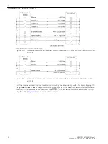
If the automatic reclosure function is controlled by the trip command, the following inputs and outputs are
recommended:
Functions
2.2 Automatic reclosure function (optional)
52
SIPROTEC 4, 7VK61, Manual
C53000-G1176-C159-5, Edition 05.2018
Summary of Contents for SIPROTEC 4 7VK61
Page 8: ...8 SIPROTEC 4 7VK61 Manual C53000 G1176 C159 5 Edition 05 2018 ...
Page 10: ...10 SIPROTEC 4 7VK61 Manual C53000 G1176 C159 5 Edition 05 2018 ...
Page 16: ...16 SIPROTEC 4 7VK61 Manual C53000 G1176 C159 5 Edition 05 2018 ...
Page 176: ...176 SIPROTEC 4 7VK61 Manual C53000 G1176 C159 5 Edition 05 2018 ...
Page 224: ...224 SIPROTEC 4 7VK61 Manual C53000 G1176 C159 5 Edition 05 2018 ...
Page 264: ...264 SIPROTEC 4 7VK61 Manual C53000 G1176 C159 5 Edition 05 2018 ...
Page 270: ...270 SIPROTEC 4 7VK61 Manual C53000 G1176 C159 5 Edition 05 2018 ...
Page 276: ...276 SIPROTEC 4 7VK61 Manual C53000 G1176 C159 5 Edition 05 2018 ...
Page 346: ...346 SIPROTEC 4 7VK61 Manual C53000 G1176 C159 5 Edition 05 2018 ...

