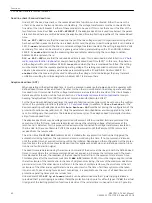
Dead line check / Reduced dead time
Under 3431 the dead line check or the reduced dead time function can be activated. Either the one or the
other can be used as the two options are contradictory. The voltage transformers must be connected to the
line side of the circuit breaker if either of these modes is to be used. If this is not the case or if neither of the
two functions is used, set
DLC or RDT
=
WITHOUT
. If the adaptive dead time is used (see below), the param-
eters mentioned here are omitted because the adaptive dead time implies the properties of the reduced dead
time.
DLC or RDT
=
DLC
means that the dead line check of the line voltage is used. It only allows reclosing after it
has been verified in advance that the line is dead. In this case, the phase-to-earth voltage limit is set in address
3441
U-dead<
below which the line is considered voltage-free (disconnected). The setting is applied in Volts
secondary. This value can be entered as a primary value when parameterizing with a PC and DIGSI. Address
3438
T U-stable
determines the measuring time available for determining the no-voltage condition.
Address 3440 is irrelevant here.
DLC or RDT
=
RDT
means that the reduced dead time is used. This is described in detail in Section
matic reclosure function (optional)
at margin heading “Reduced Dead Time (RDT)”. In this case, the phase-to-
earth voltage limit is set in address 3440
U-live>
above which the line is considered fault-free. The setting
must be smaller than the lowest expected operating voltage. The setting is applied in Volts secondary. This
value can be entered as a primary value when parameterizing with a PC and DIGSI. Address 3438
T U-
stable
defines the measuring time used to determine the voltage. It should be longer than any transient
oscillations resulting from line energization. Address 3441 is irrelevant here.
Adaptive dead time (ADT)
When operating with adaptive dead time, it must be ensured in advance that one end per line operates with
defined dead times and has an infeed. The other (or the others in multi-branch lines) may operate with adap-
tive dead time. It is essential that the voltage transformers are located on the line side of the circuit breaker.
Details about this function can be found in Section
2.2 Automatic reclosure function (optional)
at margin
heading “Adaptive Dead Time (ADT) and Close Command-transfer (Remote-CLOSE)”.
For the line end with defined dead times the number of desired reclose cycles must be set during the configu-
ration of the protection functions (Section
) in address 133
Auto Reclose
. For the
devices operating with adaptive dead time
Auto Reclose
=
ADT
must be set during the configuration of the
protection functions under address 133. Only the parameters described below are interrogated in the latter
case. No settings are then made for the individual reclosure cycles. The adaptive dead time implies function-
ality of reduced dead time.
The adaptive dead time may be voltage-controlled or Remote–CLOSE–controlled. Both are possible at the
same time. In the first case, reclosure takes place as soon as the returning voltage, after reclosure at the
remote end, is detected. For this purpose the device must be connected to voltage transformers located on
the line side. In the case of Remote-CLOSE, the autoreclosure waits until the Remote-CLOSE command is
received from the remote end.
The action time
T-ACTION ADT
(address 3433) is started after any protection function has triggered the
automatic reclosing function. The trip command must occur during this time. If no trip command is issued
until the action time has expired, reclosing will not be initiated. Depending on the configuration of the protec-
tion functions, the action time may also be omitted; this applies especially when an initiating protection func-
tion has no fault detection signal.
The dead times are determined by the reclosure command of the device at the line end with the defined dead
times. In cases where this reclosure command does not appear, e.g. because the reclosure was in the mean-
time blocked at this end, the readiness of the local device must return to the quiescent state at some time.
This takes place after the maximum wait time
T-MAX ADT
(address 3434). It must be long enough to include
the last reclosure of the remote end. In the case of single-shot reclosing, the sum of the maximum dead time
plus reclaim time of the other device is sufficient. In the case of multiple reclosure, the worst case is that all
reclosures of the other end except the last one are unsuccessful. The time of all these cycles must be taken
into account. To save having to make exact calculations, it is possible to use the sum of all dead times and all
protection operating times plus one reclaim time.
Under address 3435
ADT 1p allowed
allowed it can be determined whether 1-pole tripping is allowed
(provided that 1-pole tripping is possible). If
NO
, the protection trips 3-pole for all fault types. If
YES
, the actual
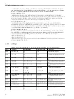
trip signal of the starting protection functions is decisive. If the reclaim time is unequal to 0 s and 1-pole trip-
Functions
2.2 Automatic reclosure function (optional)
60
SIPROTEC 4, 7VK61, Manual
C53000-G1176-C159-5, Edition 05.2018
Summary of Contents for SIPROTEC 4 7VK61
Page 8: ...8 SIPROTEC 4 7VK61 Manual C53000 G1176 C159 5 Edition 05 2018 ...
Page 10: ...10 SIPROTEC 4 7VK61 Manual C53000 G1176 C159 5 Edition 05 2018 ...
Page 16: ...16 SIPROTEC 4 7VK61 Manual C53000 G1176 C159 5 Edition 05 2018 ...
Page 176: ...176 SIPROTEC 4 7VK61 Manual C53000 G1176 C159 5 Edition 05 2018 ...
Page 224: ...224 SIPROTEC 4 7VK61 Manual C53000 G1176 C159 5 Edition 05 2018 ...
Page 264: ...264 SIPROTEC 4 7VK61 Manual C53000 G1176 C159 5 Edition 05 2018 ...
Page 270: ...270 SIPROTEC 4 7VK61 Manual C53000 G1176 C159 5 Edition 05 2018 ...
Page 276: ...276 SIPROTEC 4 7VK61 Manual C53000 G1176 C159 5 Edition 05 2018 ...
Page 346: ...346 SIPROTEC 4 7VK61 Manual C53000 G1176 C159 5 Edition 05 2018 ...

