Thermal Overload Protection 49
The thermal overload protection is designed to prevent thermal overloads from damaging the protected
equipment. The protection function represents a thermal replica of the equipment to be protected (overload
protection with memory capability). Both the previous history of an overload and the heat loss to the environ-
ment are taken into account.
Applications
•
In particular, the thermal overload protection allows the thermal status of motors, generators and trans-
formers to be monitored.
•
If an additional thermal input is available, the thermal replica may take the actual ambient or coolant
temperature into account.
Description
Thermal Replica
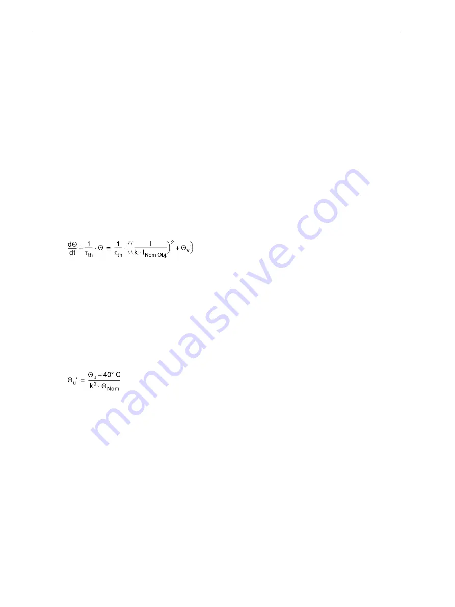
The device calculates the overtemperature in accordance with a single-body thermal replica, based on the
following differential equation:
[thermdifferentialgleichung-260602-kn, 1, en_US]
with
Θ
Present overtemperature related to the final overtemperature at maximum allowed phase
current k ·
Ι
Nom Obj.
τ
th
Thermal time constant of the protected object's heating
Ι
Present true r.m.s value of phase current
k
k–factor indicating the maximum permissible constant phase current referred to the
nominal current of the protected object
Ι
Nom Obj.
Nominal current of protected object
[formel-umgebungstemperatur-260602-kn, 1, en_US]
with
Θ
u
Measured ambient temperature or coolant temperature
Θ
Nom
Temperature at object nominal current
If the ambient or coolant temperature is not measured, a constant value of Θ
u
= 40 °C is assumed so that Θ
u
' =
0.
The protection function therefore represents a thermal replica of the equipment to be protected (overload
protection with memory capability). Both the previous history of an overload and the heat loss to the environ-
ment are taken into account.
When the calculated overtemperature reaches the first settable threshold
49 Θ ALARM
, an alarm annuncia-
tion is issued, e.g. to allow time for the load reduction measures to take place. When the calculated overtem-
perature reaches the second threshold, the protected equipment may be disconnected from the system. The
highest overtemperature calculated from the three phase currents is used as the criterion.
The maximum thermally permissible continuous current
Ι
max
is described as a multiple of the object nominal
current
Ι
Nom Obj.
:
2.11
2.11.1
Functions
2.11 Thermal Overload Protection 49
172
SIPROTEC 4, 7SJ62/64, Manual
C53000-G1140-C207-8, Edition 08.2016
Summary of Contents for SIPROTEC 4
Page 8: ...8 SIPROTEC 4 7SJ62 64 Manual C53000 G1140 C207 8 Edition 08 2016 ...
Page 18: ...18 SIPROTEC 4 7SJ62 64 Manual C53000 G1140 C207 8 Edition 08 2016 ...
Page 30: ...30 SIPROTEC 4 7SJ62 64 Manual C53000 G1140 C207 8 Edition 08 2016 ...
Page 540: ...540 SIPROTEC 4 7SJ62 64 Manual C53000 G1140 C207 8 Edition 08 2016 ...
Page 594: ...594 SIPROTEC 4 7SJ62 64 Manual C53000 G1140 C207 8 Edition 08 2016 ...
Page 720: ...720 SIPROTEC 4 7SJ62 64 Manual C53000 G1140 C207 8 Edition 08 2016 ...


