


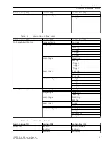

Function Group (FG)
Function (FN)
Function Block (FB)
Trend
Trend
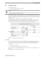
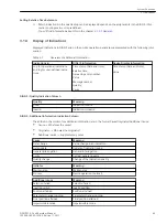
Table 2-4
Function Group PMU
Function Group (FG)
Function (FN)
Function Block (FB)
FG Phasor Measurement Unit
–
–
–
–
–
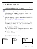
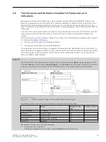
The number and type of function groups differ in the respective application templates, depending on the
application. You can add, create, or even delete user-specific function groups. You can also adapt the func-
tional scope within a function group according to the use case. You can find detailed information on this in
the DIGSI 5 Online help.
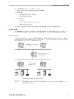
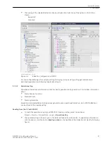
Interface Between Function Group and Measuring Point
The function groups receive the measurands of the current and voltage transformers from measuring points.
For this, the function groups are connected to one or more measuring points.
The number of measuring points and the assignment of function groups to the measuring points are preset by
the selected application template in accordance with the specific application. Therefore, this specifies which
measuring point(s) and the corresponding measurands have to be used by which function within the function
group.
The user can change the assignment as needed, that is, function groups can be assigned to any available
measuring points of the device.
You can find a detailed description of the assignment of the measuring points to the function groups in
chapter
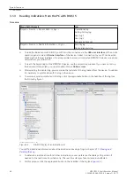
7.1.3 Step 2: Setting the Parameters and Routing in DIGSI 5
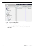
Trigger Routing – Interface between Function Group and Recorders
You can assign the trigger building blocks, which were configured in the feeder function groups flexibly to the
configured fault recorders. Each function group for feeders contains an overview of the successful assign-
ments for this purpose. In this overview this assignment can be adapted.
You can find a detailed description of the trigger assignment in chapter
7.1.3 Step 2: Setting the Parameters
under the keyword Trigger-routing.
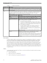
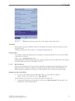
Functions, Function Blocks
Functions can be assigned to function groups. An assignment of a function to a feeder function group defines
that, for example, this function uses the measuring points of this feeder.
Functions can be further subdivided.
Functions consist, for example, of one or more function blocks:
•
Example of a function with one function block: The function Fast-scan recorder consists of the single
function block Fst-scan rec.
•
Example of a function with several function blocks: The Voltage trigger function consists of the function
blocks V Fund. Trig, Trig. V RMS, V0 Trigger, V1 Trigger and V2 Trigger
Each function block and each function (without function blocks) can be individually switched into specific
operating modes (for example, switch on/off). This is termed function control and is explained in chapter
.
To adjust the functionality to the specific application, functions and function blocks can be added, created,
and deleted (see chapter
2.2 Adjustment of Application Templates/Functional Scope
Basic Structure of the Function
2.1 Function Embedding in the Device
34
SIPROTEC 5, Fault Recorder, Manual
C53000-G5040-C018-5, Edition 11.2017
Summary of Contents for SIPROTEC 5
Page 8: ...8 SIPROTEC 5 Fault Recorder Manual C53000 G5040 C018 5 Edition 11 2017 ...
Page 18: ...18 SIPROTEC 5 Fault Recorder Manual C53000 G5040 C018 5 Edition 11 2017 ...
Page 134: ...134 SIPROTEC 5 Fault Recorder Manual C53000 G5040 C018 5 Edition 11 2017 ...
Page 212: ...212 SIPROTEC 5 Fault Recorder Manual C53000 G5040 C018 5 Edition 11 2017 ...
Page 422: ...422 SIPROTEC 5 Fault Recorder Manual C53000 G5040 C018 5 Edition 11 2017 ...
Page 426: ...426 SIPROTEC 5 Fault Recorder Manual C53000 G5040 C018 5 Edition 11 2017 ...
Page 452: ...452 SIPROTEC 5 Fault Recorder Manual C53000 G5040 C018 5 Edition 11 2017 ...
Page 490: ...490 SIPROTEC 5 Fault Recorder Manual C53000 G5040 C018 5 Edition 11 2017 ...


