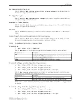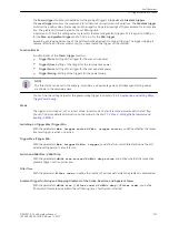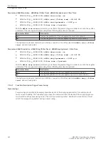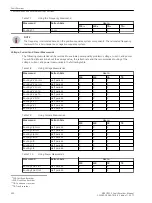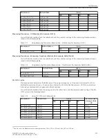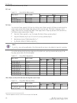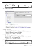
Parameter: dM/dt Rise Active - dM/dt Rise (/Filter Time) - dM/dt Rise Hysteresis - Filter Time
•
Default setting
(_:10021:103) dM/dt rise active
=
no
•
Default setting
(_:10021:107) dM/dt rise (/Filter time)
=
34.641 VA
•
Default setting
(_:10021:115) dM/dt rise hysteresis
=
0.980 p.u.
•
Default setting
(_:10021:112) Filter time
=
2 periods
With the
dM/dt rise active
parameter, you activate the gradient trigger in order to monitor the positive
gradients of the sum apparent power using the set filtering time (input in periods).
Parameter Value
Description
yes
The positive gradient of the sum apparent power is monitored.
no
The positive gradient of the sum apparent power is not monitored.
The hysteresis is preset at the factory to 0.980 p.u. (equal to 2 %) of the parameter
dM/dt rise (/Filter
time)
and can be adjusted.
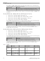
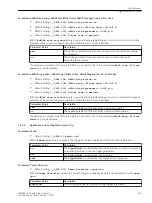
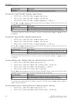
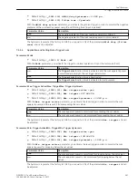
Parameter: dM/dt Drop Active - dM/dt Drop (/Filter Time) - dM/dt Drop Hysteresis - Filter Time
•
Default setting
(_:10021:104) dM/dt drop active
=
no
•
Default setting
(_:10021:108) dM/dt drop (/Filter time)
=
34.641 VA
•
Default setting
(_:10021:116) dM/dt drop hysteresis
=
0.980 p.u.
•
Default setting
(_:10021:112) Filter time
=
2 periods
With the
dM/dt drop active
parameter, you activate the gradient trigger in order to monitor the negative
gradients of the sum apparent power using the set filtering time (input in periods).
Parameter Value
Description
yes
The negative gradient of the sum apparent power is monitored.
no
The negative gradient of the sum apparent power is not monitored.
The hysteresis is preset at the factory to 0.980 p.u. (equal to 2 %) of the parameter
dM/dt drop (/Filter
time)
and can be adjusted.
Function Description Trigger Power Swing
Power Swings
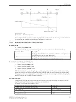
Power swings are created by temporary angle deviations of the supplying generators, for example, due to
faults or load shedding. The following figure shows the network section involved with the supplying genera-
tors A and B and the power-swing center. The term “power-swing center” describes the location on a line at
which the voltage dip is greatest during a power swing.
7.5.4.7
Fault Recorder
7.5 Trigger Functions 3-Phase
342
SIPROTEC 5, Fault Recorder, Manual
C53000-G5040-C018-5, Edition 11.2017
Summary of Contents for SIPROTEC 5
Page 8: ...8 SIPROTEC 5 Fault Recorder Manual C53000 G5040 C018 5 Edition 11 2017 ...
Page 18: ...18 SIPROTEC 5 Fault Recorder Manual C53000 G5040 C018 5 Edition 11 2017 ...
Page 134: ...134 SIPROTEC 5 Fault Recorder Manual C53000 G5040 C018 5 Edition 11 2017 ...
Page 212: ...212 SIPROTEC 5 Fault Recorder Manual C53000 G5040 C018 5 Edition 11 2017 ...
Page 422: ...422 SIPROTEC 5 Fault Recorder Manual C53000 G5040 C018 5 Edition 11 2017 ...
Page 426: ...426 SIPROTEC 5 Fault Recorder Manual C53000 G5040 C018 5 Edition 11 2017 ...
Page 452: ...452 SIPROTEC 5 Fault Recorder Manual C53000 G5040 C018 5 Edition 11 2017 ...
Page 490: ...490 SIPROTEC 5 Fault Recorder Manual C53000 G5040 C018 5 Edition 11 2017 ...

