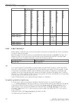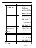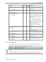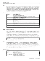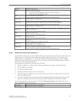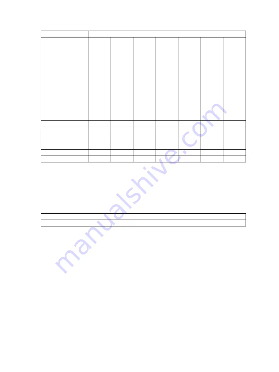
Error Responses
Group-Warning Indication Group Warning
Indication in the Operational Log
Indication in the Device-Diagnosis Log
Indication of the Life Contact
All Protection and Automation Functions
Are Inactive
Device Restart (Reset)
Fallback Mode
Defect severity 1
x
x
x
Defect severity 2
x
x
During the
starting
time of
the device
x
Defect severity 3
x
x
x
x
Defect severity 4
x
x
x
Defect Severity 1
Defect severity 1 faults allow the continued safe operation of the device. Defect severity 1 faults are indicated.
The device remains in operation.
When the supervision functions pick up, corrupted data and signals are marked as invalid. In this way, the
affected functions can go into a secure state. Whether functions are blocked is decided in the appropriate
function itself. For more detailed information, refer to the function descriptions.
Live status contact
Remains activated
Red error LED
Is not activated
Log
For every device fault, a corresponding supervision indication is generated. The device records these indica-
tions with a real-time stamp in the operational log. In this way they are available for further analyses. If super-
visions in the communication interfaces area of the device pick up, there is a separate communication log
available for each port. Extended diagnostic indications and measured values are available there. The device-
diagnosis log contains expanded fault descriptions. There you also receive recommendations of corresponding
corrective measures for each detected device error.
There is further information on handling the logs in chapter
.
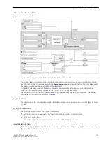
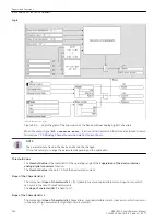
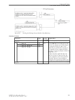
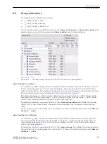
Group-Warning Indication Group Warning
In the delivery condition, all supervision indications of Defect Severity 1 are routed to the signal
(_:301)
Group warning
. In this way, a device error can be indicated with only one indication. The majority
of supervision indications are permanently connected to the
Group warning
(Group warning column =
fixed). However, some supervision indications are routed flexibly to the
Group warning
via a CFC chart
(Group warning column = CFC). If necessary, you can remove again the routings via a CFC chart from the
group indication.
In delivery condition, the
Group warning
is prerouted to an LED.
The following logic shows the context.
8.8.2
Supervision Functions
8.8 Error Responses and Corrective Measures
402
SIPROTEC 5, Fault Recorder, Manual
C53000-G5040-C018-5, Edition 11.2017
Summary of Contents for SIPROTEC 5
Page 8: ...8 SIPROTEC 5 Fault Recorder Manual C53000 G5040 C018 5 Edition 11 2017 ...
Page 18: ...18 SIPROTEC 5 Fault Recorder Manual C53000 G5040 C018 5 Edition 11 2017 ...
Page 134: ...134 SIPROTEC 5 Fault Recorder Manual C53000 G5040 C018 5 Edition 11 2017 ...
Page 212: ...212 SIPROTEC 5 Fault Recorder Manual C53000 G5040 C018 5 Edition 11 2017 ...
Page 422: ...422 SIPROTEC 5 Fault Recorder Manual C53000 G5040 C018 5 Edition 11 2017 ...
Page 426: ...426 SIPROTEC 5 Fault Recorder Manual C53000 G5040 C018 5 Edition 11 2017 ...
Page 452: ...452 SIPROTEC 5 Fault Recorder Manual C53000 G5040 C018 5 Edition 11 2017 ...
Page 490: ...490 SIPROTEC 5 Fault Recorder Manual C53000 G5040 C018 5 Edition 11 2017 ...

