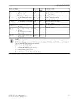


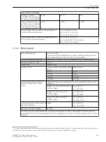
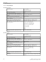
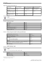


Integrated Power Supply
1/6 plug-in module
assembly without plug-in
modules (modules CB202)
3.5 W
14 VA
7 VA
Plug-in module for base
module or plug-in module
assembly (for example,
communication module)
< 5 W
< 6 VA
< 6 VA
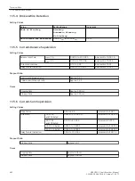
Stored-energy time for auxiliary voltage outage or
short circuit, modular devices
For V ≥ DC 24 V ≥ 50 ms
For V ≥ DC 110 V ≥ 50 ms
For V ≥ AC 115 V ≥ 50 ms
Stored-energy time for auxiliary voltage outage or
short circuit, non-modular devices
For V ≥ DC 24 V ≥ 20 ms
For V ≥ DC 60 V/DC 110 V ≥ 50 ms
For V ≥ AC 115 V ≥ 200 ms
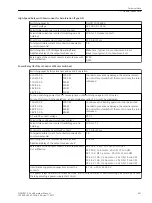
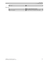
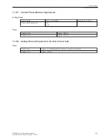
Binary Inputs
Rated voltage range
DC 24 V to 250 V
The binary inputs of SIPROTEC 5 are bipolar with the exception of the
binary inputs on the IO230, the IO231, and the IO233.
Current consumption, excited
Approx. DC 0.6 mA to 1.8 mA (independent of the control voltage)
Power consumption, max.
0.6 VA
Pickup time
Approx. 3 ms
Dropout time
20
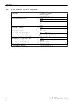
Capacitive load (supply-line capaci-
tance)
Dropout time
< 5 nF
< 4 ms
< 10 nF
< 6 ms
< 50 nF
< 10 ms
< 220 nF
< 35 ms
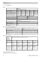
Control voltage for all modules
with binary inputs except the
IO233
Adapt the binary-input threshold to be set in the device to the control
voltage.
Range 1 for 24 V, 48 V, and 60 V
Control voltage
V
low
≤ DC 10 V
V
high
≥ DC 19 V
Range 2 for 110 V and 125 V
Control voltage
V
low
≤ DC 44 V
V
high
≥ DC 88 V
Range 3 for 220 V and 250 V
Control voltage
V
low
≤ DC 88 V
V
high
≥ DC 176 V
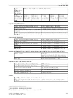
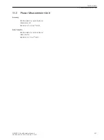
Control voltage for binary inputs of
the IO233 modules
Range
V
low
≤ DC 85 V
V
high
≥ DC 105 V
Maximum permitted voltage
DC 300 V
The binary inputs contain interference suppression capacitors. In order to ensure EMC immunity, use the
terminals shown in the terminal diagrams/connection diagrams to connect the binary inputs to the common
potential.
11.1.2
20
For time-critical applications with low-active signals, consider the specified dropout times. If necessary, provide for active discharge of
the binary input (for example, a resistor in parallel to the binary input or using a change-over contact).
Technical Data
11.1 General Device Data
SIPROTEC 5, Fault Recorder, Manual
429
C53000-G5040-C018-5, Edition 11.2017
Summary of Contents for SIPROTEC 5
Page 8: ...8 SIPROTEC 5 Fault Recorder Manual C53000 G5040 C018 5 Edition 11 2017 ...
Page 18: ...18 SIPROTEC 5 Fault Recorder Manual C53000 G5040 C018 5 Edition 11 2017 ...
Page 134: ...134 SIPROTEC 5 Fault Recorder Manual C53000 G5040 C018 5 Edition 11 2017 ...
Page 212: ...212 SIPROTEC 5 Fault Recorder Manual C53000 G5040 C018 5 Edition 11 2017 ...
Page 422: ...422 SIPROTEC 5 Fault Recorder Manual C53000 G5040 C018 5 Edition 11 2017 ...
Page 426: ...426 SIPROTEC 5 Fault Recorder Manual C53000 G5040 C018 5 Edition 11 2017 ...
Page 452: ...452 SIPROTEC 5 Fault Recorder Manual C53000 G5040 C018 5 Edition 11 2017 ...
Page 490: ...490 SIPROTEC 5 Fault Recorder Manual C53000 G5040 C018 5 Edition 11 2017 ...