

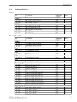


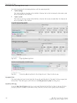
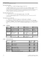
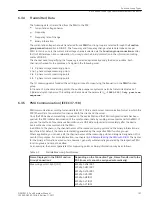

Operational Measured Values
The operational measured values are always present in the Voltage/current 1-phase function group and
cannot be removed.
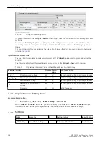
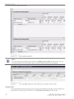
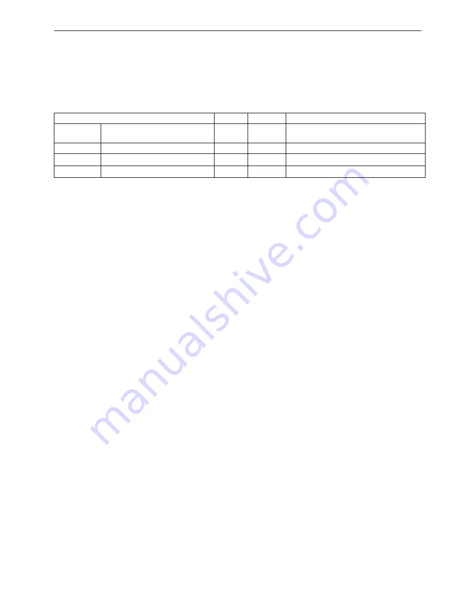
The following table shows the operational measured values of the Voltage/current 1-phase function group:
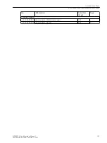
Table 6-2
Operational Measured Values of the Voltage/Current 1-Phase Function Group
Measured Values
Primary
Secondary % Referenced to
I
1-phase current
A
A
Rated operating current of the primary
values
V
1-phase voltage
kV
V
Rated operating voltage of primary values/√3
V
0
Zero-sequence voltage
kV
V
Rated operating voltage of primary values/√3
V
N
Residual voltage
kV
V
Rated operating voltage of primary values/√3
The operational measured values are explained in more detail in chapter
9.3 Operational Measured Values
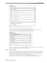
Application and Setting Notes
Parameter: Rated current
•
Default setting
(_:9421:101) Rated current
=
1000 A
With the
Rated current
parameter, you can set the primary rated current. The
Rated current
specified
here is the reference value for the percentage-measured values and setting values made in percentages.
If the device works with the IEC 61850 protocol, then you change only the setting value of the parameter via
DIGSI 5 and not directly on the device. If you change the setting value directly on the device, then the
IEC 61850 configuration of the metered values can be faulty.
Parameter: Rated voltage
•
Default setting
(_:9421:102) Rated voltage
=
400.00 kV
With the
Rated voltage
parameter, you can set the primary rated voltage. The
Rated voltage
set here is
the reference value for the percentage-measured values and setting values made in percentages.
If the device works with the IEC 61850 protocol, then you change only the setting value of the parameter via
DIGSI 5 and not directly on the device. If you change the setting value directly on the device, then the
IEC 61850 configuration of the metered values can be faulty.
Parameter: Rated apparent power
•
Default setting
(_:9421:103) Rated apparent power
=
692.82 MVA
.
The parameter
Rated apparent power
is calculated depending on other parameters and cannot be
directly changed.
Parameter: Power-sys. neutral point
•
Default setting
(_:9451:149) Power-sys. neutral point
=
grounded
With the
Power-sys. neutral point
parameter, you specify whether the system neutral is
grounded
,
isolated
or
suppress. coil grounded
(grounded via arc-suppression coil). Currently, the parameter
does not affect any protection function; only if the Automatic reclosing function uses the voltage measure-
ment.
Parameter:
P, Q sign
•
Default setting
(_:9421:150) P, Q sign
=
not reversed
The power and energy values are defined by the manufacturer such that power in the direction of the
protected object is considered positive. You can also define the power output by the protected object (for
6.2.3
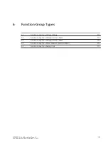
Function-Group Types
6.2 Function-Group Type Voltage/current 1-Phase
SIPROTEC 5, Fault Recorder, Manual
143
C53000-G5040-C018-5, Edition 11.2017
Summary of Contents for SIPROTEC 5
Page 8: ...8 SIPROTEC 5 Fault Recorder Manual C53000 G5040 C018 5 Edition 11 2017 ...
Page 18: ...18 SIPROTEC 5 Fault Recorder Manual C53000 G5040 C018 5 Edition 11 2017 ...
Page 134: ...134 SIPROTEC 5 Fault Recorder Manual C53000 G5040 C018 5 Edition 11 2017 ...
Page 212: ...212 SIPROTEC 5 Fault Recorder Manual C53000 G5040 C018 5 Edition 11 2017 ...
Page 422: ...422 SIPROTEC 5 Fault Recorder Manual C53000 G5040 C018 5 Edition 11 2017 ...
Page 426: ...426 SIPROTEC 5 Fault Recorder Manual C53000 G5040 C018 5 Edition 11 2017 ...
Page 452: ...452 SIPROTEC 5 Fault Recorder Manual C53000 G5040 C018 5 Edition 11 2017 ...
Page 490: ...490 SIPROTEC 5 Fault Recorder Manual C53000 G5040 C018 5 Edition 11 2017 ...


