Error Description
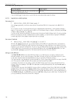
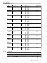
Status Health
A communication module has not received any more
data from the RTD unit for 9 sec.
Warning
The
Failure
signal is set as soon as one of the sensor function blocks reports a failure.
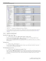
Application and Setting Notes
Parameter: Port
•
Default setting
(_:2311:103) Port
=
port J
Use the
Port
parameter to define over which port the external RTD unit is connected to the SIPROTEC 5
device.
If you want to connect the external RTD unit to the integrated Ethernet interface, set the parameter
Port
=
Port J
. If you want to connect the external RTD unit to an Ethernet plug-in module, set the parameter
Port
=
Port F
,
Port E
,
Port P
, or
Port N
.
You can connect directly the RTD unit to the device via the internal 10-Mbit Ethernet port J. If you operate the
RTD unit on another port via a 100-Mbit communication module, you need an interconnected 10/100-Mbit
autosensing switch, which adapts transmission rates accordingly.
Parameter: IP address
•
Default setting
(_:2311:104) IP address
=
10.16.60.1
With the
IP address
parameter, you set the IP address of the RTD unit connected to the communication
module via the SUP protocol. Every RTD unit has to be assigned a unique IP address. The IP address to be set
depends on your network configuration. You can set any valid IPv4 address that does not cause conflicts with
other IP addresses in the network. Set an appropriate IP address first at the Ziehl TR1200 IP RTD unit. Then
specify the
IP address
parameter for the communication module to the same address.
Settings on the RTD Unit
The Ziehl TR1200 IP RTD unit is set with the front keys or in a Web browser on a laptop computer via its
Ethernet interface. Set the connection type of the sensors (3-wire connection or resistance value for 2-wire
connection), the idle state of the fault-indication relay, as well as the IP interface setting.
The code lock has to be switched off for parameterization. This is only possible using the front keys of the RTD
unit. The code lock is off (switched off) in as-delivered condition and has pin 504.
For detailed information on the settings, refer to the TR1200 IP manual that comes with the RTD unit. The
documents are also available in the SIPROTEC download area (http://www.siprotec.de) under Accessories ->
7XV5662-xAD.
For an Ethernet connection to a SIPROTEC 5 device communicating with the RTD unit TR1200 IP via the SUP
protocol (Slave Unit Protocol), the
Modbus TCP
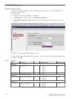
setting must be activated in the RTD unit. You can activate
the Modbus TCP protocol using the function keys under the TcP - mod menu item or with the Web browser in
the TCP/UDP Config tab. The RTD (RTD protocol) and UDP Port settings have no effect here. The Modbus TCP
port is permanently set to 502 and cannot be changed.
6.5.7.4
Function-Group Types
6.5 Function-Group Type Analog Units
198
SIPROTEC 5, Fault Recorder, Manual
C53000-G5040-C018-5, Edition 11.2017
Summary of Contents for SIPROTEC 5
Page 8: ...8 SIPROTEC 5 Fault Recorder Manual C53000 G5040 C018 5 Edition 11 2017 ...
Page 18: ...18 SIPROTEC 5 Fault Recorder Manual C53000 G5040 C018 5 Edition 11 2017 ...
Page 134: ...134 SIPROTEC 5 Fault Recorder Manual C53000 G5040 C018 5 Edition 11 2017 ...
Page 212: ...212 SIPROTEC 5 Fault Recorder Manual C53000 G5040 C018 5 Edition 11 2017 ...
Page 422: ...422 SIPROTEC 5 Fault Recorder Manual C53000 G5040 C018 5 Edition 11 2017 ...
Page 426: ...426 SIPROTEC 5 Fault Recorder Manual C53000 G5040 C018 5 Edition 11 2017 ...
Page 452: ...452 SIPROTEC 5 Fault Recorder Manual C53000 G5040 C018 5 Edition 11 2017 ...
Page 490: ...490 SIPROTEC 5 Fault Recorder Manual C53000 G5040 C018 5 Edition 11 2017 ...


