[scapp7ke-200515, 1, en_US]
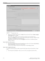
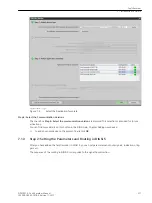
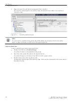
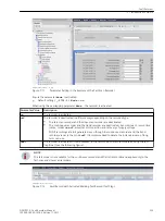
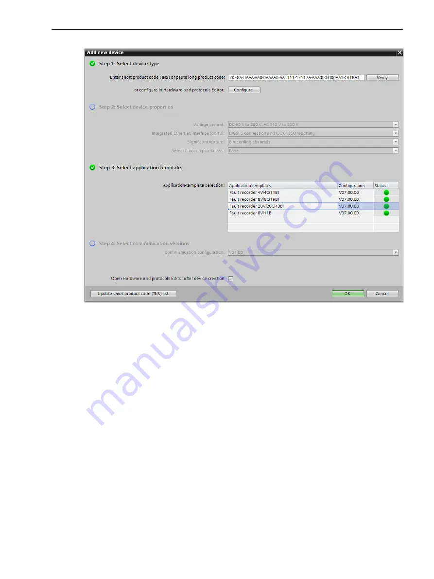
Figure 7-4
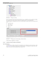
Select the Application Template
Step 4: Select the Communication Versions
The check box Step 4: Select the communication versions is dimmed. This selection is intended for future
activations.
You can find more details on this button in the DIGSI Help, Chapter Adding new device.
²
To add your new device to the project, finally click OK.
Step 2: Setting the Parameters and Routing in DIGSI 5
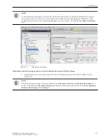
After you have added the fault recorder in DIGSI 5, you can set parameters and route signals, indications, trig-
gers, etc.
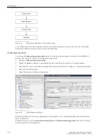
The sequence of the routing in DIGSI 5 corresponds to the signal flow direction.
7.1.3
Fault Recorder
7.1 Introduction to DIGSI 5
SIPROTEC 5, Fault Recorder, Manual
217
C53000-G5040-C018-5, Edition 11.2017
Summary of Contents for SIPROTEC 5
Page 8: ...8 SIPROTEC 5 Fault Recorder Manual C53000 G5040 C018 5 Edition 11 2017 ...
Page 18: ...18 SIPROTEC 5 Fault Recorder Manual C53000 G5040 C018 5 Edition 11 2017 ...
Page 134: ...134 SIPROTEC 5 Fault Recorder Manual C53000 G5040 C018 5 Edition 11 2017 ...
Page 212: ...212 SIPROTEC 5 Fault Recorder Manual C53000 G5040 C018 5 Edition 11 2017 ...
Page 422: ...422 SIPROTEC 5 Fault Recorder Manual C53000 G5040 C018 5 Edition 11 2017 ...
Page 426: ...426 SIPROTEC 5 Fault Recorder Manual C53000 G5040 C018 5 Edition 11 2017 ...
Page 452: ...452 SIPROTEC 5 Fault Recorder Manual C53000 G5040 C018 5 Edition 11 2017 ...
Page 490: ...490 SIPROTEC 5 Fault Recorder Manual C53000 G5040 C018 5 Edition 11 2017 ...

