background image

Supervision of Communication Connections

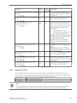
SIPROTEC 5 devices offer extensive communication possibilities via fixed and optional interfaces. Beyond the
hardware supervision of the communication plug-in modules the transferred data must be monitored with
respect to their consistency, failure, or outage.

Supervision

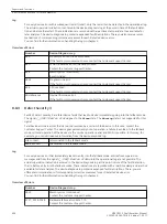
With the supervision of the communication connections, every communication port is monitored selectively.

Failures are detected and indicated via the operational log. The device remains in operation!

Each port additionally is equipped with a separate communication log, with which details of the failures
(for example, error rate) are displayed.

Marking Fault Signals/Data

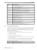
The signals/data affected by the failure are marked as invalid. In this way, the affected protection functions
can go into a secure state. In the following, some examples are named:

GOOSE signals can automatically be set to defined values in case of disturbed IEC 61850 communication.

Disturbed time-synchronization signals can lead to an automatic change of the source of time synchroni-
zation.

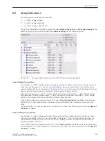
Normally, you can correct communication failures by checking the external connections or by replacing the
affected communication modules. In chapter to 

8.8.4 Defect Severity 3

, you will find the detailed description,

in tabular form, of the error responses. Corresponding corrective measures can also be found there.

8.7

Supervision Functions
8.7 Supervision of Communication Connections

400

SIPROTEC 5, Fault Recorder, Manual

C53000-G5040-C018-5, Edition 11.2017

Summary of Contents for SIPROTEC 5

Page 1: ...ource Software Table of Contents Introduction 1 Basic Structure of the Function 2 System Functions 3 Applications 4 Power System Data 5 Function Group Types 6 Fault Recorder 7 Supervision Functions 8 Measured and Energy Values 9 Functional Tests 10 Technical Data 11 Appendix A Glossary Index ...

Page 2: ...lations nor does it change these All obligations of Siemens AG are stated in the relevant contractual agree ments Siemens AG reserves the right to revise this document from time to time Document version C53000 G5040 C018 5 03 Edition 11 2017 Version of the product described V7 50 and higher Copyright Copyright Siemens AG 2017 All rights reserved The disclosure duplication distribution and editing ...

Page 3: ...ation dwprefdm 221012 01 tif 3 en_US Device manuals Each Device manual describes the functions and applications of a specific SIPROTEC 5 device The printed manual and the online help for the device have the same informational structure Hardware manual The Hardware manual describes the hardware building blocks and device combinations of the SIPROTEC 5 device family Operating manual The Operating ma...

Page 4: ...al areas as well as operating sequences with tasks based on practical operation and a brief explanation SIPROTEC 5 catalog The SIPROTEC 5 catalog describes the system features and the devices of SIPROTEC 5 Selection guide for SIPROTEC and Reyrolle The selection guide offers an overview of the device series of the Siemens protection devices and a device selection table Indication of Conformity This...

Page 5: ...ipment module or device However it comprises important information that must be followed for personal safety as well as to avoid material damage Information is highlighted and illustrated as follows according to the degree of danger DANGER DANGER means that death or severe injury will result if the measures specified are not taken Comply with all instructions in order to avoid death or severe inju...

Page 6: ...in combination with third party equipment recommended and approved by Siemens Problem free and safe operation of the product depends on the following Proper transport Proper storage setup and installation Proper operation and maintenance When electrical equipment is operated hazardous voltages are inevitably present in certain parts If proper action is not taken death severe injury or property dam...

Page 7: ...d of at least 3 years since purchase of the Product We are liable for the Product including the Open Source Software contained in it pursuant to the license conditions applicable to the Product Any liability for the Open Source Software beyond the program flow intended for the Product is explicitly excluded Furthermore any liability for defects resulting from modifications to the Open Source Softw...

Page 8: ...8 SIPROTEC 5 Fault Recorder Manual C53000 G5040 C018 5 Edition 11 2017 ...

Page 9: ...Reading Indications on the On Site Operation Panel 42 3 1 3 Reading Indications from the PC with DIGSI 5 44 3 1 4 Display of Indications 45 3 1 5 Logs 46 3 1 5 1 General 46 3 1 5 2 Operational Log 47 3 1 5 3 User Defined Log 49 3 1 5 4 Sequence of Events Log 52 3 1 6 Setting History Log 54 3 1 7 Communication Log 56 3 1 8 Security Log 57 3 1 9 Device Diagnosis Log 59 3 1 10 Saving and Deleting the...

Page 10: ...ication Template and Functional Scope for the Fault Recorder 105 5 Power System Data 109 5 1 Overview 110 5 2 Structure of the Power System Data 111 5 3 Application and Setting Notes General Settings 112 5 4 Application and Setting Notes for Measuring Point Current 3 Phase I 3ph 113 5 5 Application and Setting Notes for Measuring Point Current 1 Phase I 1ph 116 5 6 Application and Setting Notes fo...

Page 11: ...et 173 6 5 3 1 Overview 173 6 5 3 2 Structure of the Function 173 6 5 3 3 Communication with 20 mA Unit Ethernet 174 6 5 3 4 Application and Setting Notes 175 6 5 3 5 20 mA Channel 175 6 5 3 6 Application and Setting Notes 178 6 5 3 7 Settings 179 6 5 3 8 Information List 180 6 5 4 20 mA Unit Serial 180 6 5 4 1 Overview 180 6 5 4 2 Application and Setting Notes 180 6 5 4 3 Settings 182 6 5 4 4 Inf...

Page 12: ...e Function Group 231 7 2 3 Function Description 232 7 2 4 Application and Setting Notes General Settings 234 7 2 5 Time Jumps 235 7 2 6 Fast Scan Recorder 236 7 2 6 1 Overview of Functions 236 7 2 6 2 Structure of the Function 236 7 2 6 3 Function Description 236 7 2 6 4 Application and Setting Notes 238 7 2 6 5 Settings 240 7 2 6 6 Information List 240 7 2 7 Slow Scan Recorder 241 7 2 7 1 Overvie...

Page 13: ...tions 271 7 4 1 2 Structure of the Function 271 7 4 1 3 Function Description 271 7 4 1 4 Application and Setting Notes Trig V RMS RMS Value 273 7 4 1 5 Application and Setting Notes Trig V Fund Fundamental Component 274 7 4 1 6 Settings 276 7 4 1 7 Information List 277 7 4 2 Current Trigger 277 7 4 2 1 Overview of Functions 277 7 4 2 2 Structure of the Function 277 7 4 2 3 Function Description 278...

Page 14: ...quency Trigger 331 7 5 3 1 Overview of Functions 331 7 5 3 2 Structure of the Function 331 7 5 3 3 Function Description 332 7 5 3 4 Application and Setting Notes Frequency Trigger 333 7 5 3 5 Settings 334 7 5 3 6 Information List 335 7 5 4 Power Trigger 335 7 5 4 1 Overview of Functions 335 7 5 4 2 Structure of the Function 335 7 5 4 3 Function Description 336 7 5 4 4 Application and Setting Notes...

Page 15: ...72 8 3 2 Voltage Balance Supervision 372 8 3 2 1 Overview of Functions 372 8 3 2 2 Structure of the Function 372 8 3 2 3 Function Description 372 8 3 2 4 Application and Setting Notes 374 8 3 2 5 Settings 374 8 3 2 6 Information List 374 8 3 3 Voltage Sum Supervision 375 8 3 3 1 Overview of Functions 375 8 3 3 2 Structure of the Function 375 8 3 3 3 Function Description 375 8 3 3 4 Application and...

Page 16: ... Sum 394 8 4 2 1 Overview of Functions 394 8 4 2 2 Structure of the Function 395 8 4 2 3 Function Description 395 8 5 Supervision of Device Firmware 398 8 6 Supervision of Hardware Configuration 399 8 7 Supervision of Communication Connections 400 8 8 Error Responses and Corrective Measures 401 8 8 1 Overview 401 8 8 2 Defect Severity 1 402 8 8 3 Defect Severity 2 405 8 8 4 Defect Severity 3 406 8...

Page 17: ...sion 441 11 5 3 Voltage Phase Rotation Supervision 441 11 5 4 Broken Wire Detection 442 11 5 5 Current Balance Supervision 442 11 5 6 Current Sum Supervision 442 11 5 7 Current Phase Rotation Supervision 443 11 5 8 Analog Channel Supervision via Fast Current Sum 443 11 6 Operational Measured Values and Statistical Values 444 11 7 CFC 448 A Appendix 453 A 1 Order Configurator and Order Options 454 ...

Page 18: ...18 SIPROTEC 5 Fault Recorder Manual C53000 G5040 C018 5 Edition 11 2017 ...
Page 19: ...al 20 1 2 Properties of SIPROTEC 5 21 1 3 Properties of the Fault Recorder 23 1 4 Parameterization and Analysis Software 25 1 5 Scope of Functions 28 1 SIPROTEC 5 Fault Recorder Manual 19 C53000 G5040 C018 5 Edition 11 2017 ...
Page 20: ...le information from secondary equip ment using fault recorders is therefore essential This is the only way to ensure today s currently high levels of reliability and availability in electricity transmission and distribution systems for the future as well A new era has begun for fault recording with the introduction of the SIPROTEC 5 series The 7KE85 fault recorder was developed especially for the ...

Page 21: ...possible via the device interface Battery buffered synchronizable clock Microcomputer System All device functions are processed in the microcomputer system This includes for example Filtering and preparation of the measurands Constant monitoring of the measurands Monitoring of the trigger conditions for the individual functions Querying of limiting values and time outs Controlling of signals for t...

Page 22: ...n integrated or detached operation panel LEDs and an LC display on the front provide infor mation on the device function and report events states and measured values In conjunction with the LC display the integrated keypad enables on site operation of the device All device information such as setting parameters operating and fault indications or measured values can be displayed and setting paramet...

Page 23: ... 4 15 standards Poor power quality can lead to a power failure Effects on power quality consist of and are created chiefly by large loads for example industrial processes changes in the current network status switching operations and by external effects for example lightning Power quality standards for example EN 50160 are used to specify limits for electric measurands within which connected devic...

Page 24: ...rt Specifying the limits for electrical measurands Monitoring power network quality Power Quality Monitoring according to EN 50160 Measuring flicker according to IEC 61000 4 15 Additional functions for simple tests and for commissioning Introduction 1 3 Properties of the Fault Recorder 24 SIPROTEC 5 Fault Recorder Manual C53000 G5040 C018 5 Edition 11 2017 ...
Page 25: ...rmation from secondary equip ment using fault recorders is therefore essential This is the only way to ensure today s currently high levels of reliability and availability in electricity transmission and distribution systems for the future as well Addition ally the growing use of power electronics often has a noticeable impact on power quality The result is poor power quality which can cause inter...

Page 26: ...rmat Ethernet network monitoring for example based on SNMP Data exchange via OPC for the connection to office desktop computers Secured data access via a user management Redundant structure of the system on different levels Test and diagnostic functions Export of fault records via COMTRADE Export of PQ data via PQDIF Notification via e mail and SMS dw7keebe 161012 01 tif 2 en_US Figure 1 1 Overvie...

Page 27: ...n its local source archive This archive data can be directly evaluated by one or several SICAM PQ Analyzer s Collector Archive In distributed systems with one or several Full Servers the data in the source archives is collected by the SICAM PQ Analyzer Collector and stored in a central Collector archive on an archive computer This archive data is evaluated by one or more SICAM PQ Analyzer s dwcoll...

Page 28: ...ated with the history of the RMS value of the voltage and the current Power swing cycles between the power plant and transmission system can lead to severe damage to the generator if they are not detected in time and shut down This job is performed by the distance protec tion equipment With the use of the Slow scan recorder function the network status can be precisely recorded before during and af...

Page 29: ...wing With these functions the long term stability problems can be analyzed in detail These measurements form a solid foundation for expensive invest ments such as the procurement of compensation systems SVC The availability and quality of the power supply is very important for power distribution utilities To monitor the voltage quality also known as Power Quality PQ over a long period of time the ...

Page 30: ...eed line or transformer Possible busbars 2 Power generation decentral power generation Busbars transformers or generator connection 3 Forwarding distribution system Busbars for example if the busbar belongs to the transmis sion company and is run by it 4 Forwarding infeed line or trans former Decentral line connection for example if the line belongs to the transmission company and is run by it 5 F...

Page 31: ...ding in the Device 32 2 2 Adjustment of Application Templates Functional Scope 35 2 3 Function Control 37 2 4 Text Structure and Reference Number for Parameter and Indications 39 2 SIPROTEC 5 Fault Recorder Manual 31 C53000 G5040 C018 5 Edition 11 2017 ...
Page 32: ...roups This simplifies handling of functions adding and creating The function groups are assigned primary objects such as feeders with current and voltage transformers Further more special function group functionalities such as all recorders found in DIGSI 5 under Recording can be summarized The function groups bundle functions with regard to the following basic tasks Assignment of functions to cur...

Page 33: ... S Sum Trig Recorder routing VI Routing f Routing I Routing power Routing V FG Voltage current 1 phase Frequency trigger Frq Trigger Voltage trigger V Fund Trig V RMS Trig Current trigger I Fund Trig I RMS Trig Power trigger P trigger Q trigger Recorder routing VI Routing f Routing I Routing power Routing V Table 2 3 Function Group Recorder Function Group FG Function FN Function Block FB FG Record...

Page 34: ...ecorders You can assign the trigger building blocks which were configured in the feeder function groups flexibly to the configured fault recorders Each function group for feeders contains an overview of the successful assign ments for this purpose In this overview this assignment can be adapted You can find a detailed description of the trigger assignment in chapter 7 1 3 Step 2 Setting the Parame...

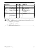
Page 35: ... i NOTE If you delete a parameterized function group function or function block from the device all settings and routings will be lost The function group function or function block can be added again but then the default settings are active In most cases the adjustment of the functional scope consists of adding and deleting functions tripping stages and function blocks As previously described the ...

Page 36: ...xample with DIGSI 5 or the SIPROTEC 5 Configurator http www energy siemens com hq de automatisierung stromuebertragung verteilung schutz siprotec5 bestellkonfigurator htm Order the additional function points from your local distributor or at http www energy siemens com Siemens will provide you with a signed license file for your device either via e mail or for downloading Use DIGSI 5 to load the s...

Page 37: ...hese modes The function control is shown in the following figure It is standardized for all fault recorder functions Therefore this control is not discussed further in the individual function descriptions losteuer 161012 01 tif 1 en_US Figure 2 1 General Control of a Recorder Function State Control You can control the state of a function via the parameter Mode and the input superordinate state You...

Page 38: ...he test state only by switching the entire device to test mode Protocol Indication and measured value are transmitted with set test bit provided that the protocol supports this functionality If an object is transmitted as a GOOSE indication the test bit is set spon taneously and the GOOSE indication is transmitted immediately The receiver of the GOOSE indication is automatically notified of transm...

Page 39: ...all hierarchy levels are always available Function Group and Function block are optional Since the same type of function groups functions as well as function blocks can be created several times a so called instance number is added to these elements EXAMPLE The structure of the text and reference number is shown for the parameter dM dt rise active and the indication Health of the function Voltage t...

Page 40: ...luding the instance numbers Parameter Number VI 3 phase Voltage trigger V Fund Trig dM dt rise active 21 _1551 _9571 _103 Indication Number VI 3 phase Voltage trigger V Fund Trig Health 21 _1551 _9571 _53 The structure is simplified accordingly for parameter and indications with fewer hierarchy levels Basic Structure of the Function 2 4 Text Structure and Reference Number for Parameter and Indicat...

Page 41: ...3 3 Processing Quality Attributes 67 3 4 Date and Time Synchronization 82 3 5 User Defined Objects 87 3 6 Other Functions 92 3 7 General Notes for Setting the Threshold Value of Trigger Functions 95 3 SIPROTEC 5 Fault Recorder Manual 41 C53000 G5040 C018 5 Edition 11 2017 ...
Page 42: ...xternal request in the form of a general interrogation In DIGSI 5 indications can be tracked spontaneously in online operation in a special indication window Indications can be made accessible to higher level control systems through mapping on various communication protocols i i NOTE All indications are assigned to certain device functions The text of each indication contains the corre sponding fu...

Page 43: ...at the top of the list The selected indication is shown with a dark background Which indications can be shown in the selected log depends on the assignments in the DIGSI 5 informa tion routing matrix or is pre defined You will find information about this in the chapter 3 1 5 1 General Every indication contains date time and its state as additional information In some logs you are given the option ...

Page 44: ...roject you can also attain this via Online access After selecting the desired log you are shown the last state of the log loaded from the device To update it is necessary to synchronize with the log in the device To execute a synchronization with the logs click the appropriate button in the headline of the log see the following figure sc7kemel 220213 01 tif 1 en_US Figure 3 2 DIGSI 5 Display of an...

Page 45: ...s valid invalid Indication is invalid DIGSI 5 Additional Information Indication Column The entries in the column for additional information are in the format Cause Originator Additional Cause Cause What was the cause Originator Who was the originator Additional cause Supplementary notes Cause Meaning Data change Value change in an indication Data update Update of indication value General interroga...

Page 46: ...ccess with safety relevance Device diagnosis log Error of the device software hardware and the connection circuits Communication Log Status of communication interfaces Administering Logs Logs have a ring structure and are automatically managed If the maximum capacity of a log is exhausted the oldest entries disappear before the newest entries During a supply voltage failure recorded data are secur...

Page 47: ...State of device functions Measured data Power system data Exceeding or dropping below limiting values generates as an operational indication Up to 2000 indications can be stored in the operational log Reading from the PC with DIGSI 5 To reach the operational log of your SIPROTEC 5 device use the project tree window Project Device Process Data Logs Operational log The operational log is shown to yo...

Page 48: ...erational log via the main menu use the navigation keys of the on site operation panel Main Menu Indications Operational indications You can navigate on the on site operation panel using the navigation keys top bottom inside the displayed indication list System Functions 3 1 Indications 48 SIPROTEC 5 Fault Recorder Manual C53000 G5040 C018 5 Edition 11 2017 ...

Page 49: ...ndividually at any time User Defined Log With the user defined log up to 2 you have the possibility of individual indication logging parallel to the operational log This is helpful for example in special monitoring tasks but also in the classification into different areas of responsibility of the logs Up to 200 indications can be stored in the user defined log Reading from the PC with DIGSI 5 To r...

Page 50: ...user specific logs from the main menu use the navigation keys of the on site operation panel Main Menu Indications User log 1 2 You can navigate on the on site operation panel using the navigation keys top bottom inside the displayed indication list System Functions 3 1 Indications 50 SIPROTEC 5 Fault Recorder Manual C53000 G5040 C018 5 Edition 11 2017 ...

Page 51: ... be deleted Read about it in the chapter 3 1 10 Saving and Deleting the Log Configuration of a User Defined Log The indication scope of a created user specific log can be configured freely in the associated column of the information routing matrix of DIGSI 5 Target Log V1 or V2 System Functions 3 1 Indications SIPROTEC 5 Fault Recorder Manual 51 C53000 G5040 C018 5 Edition 11 2017 ...

Page 52: ...maximum number of entries the oldest entries will be overwritten Reading from the PC with DIGSI 5 Use the project tree window to access the sequence of events for your SIPROTEC 5 device Project Device Process Data Logs Sequence of events The sequence of events log is shown to you in the last loaded state from the device To update the device synchronization with the device click the button Read log...

Page 53: ...u can navigate within the displayed indication list using the navigation keys up down on the on site operation panel scsoehmi 040713 01 tif 1 en_US Figure 3 10 Reading the Sequence of Events on the On site Operation Panel of the Device Deletability The sequence of events for your SIPROTEC 5 device can be deleted To know more about this read chapter 3 1 10 Saving and Deleting the Log System Functio...

Page 54: ...the setting history log Reading from the PC with DIGSI 5 To reach the log for parameter changes of your SIPROTEC 5 device use the project tree window Project Device Process Data Log Setting history log The setting history log is shown to you in the state last loaded from the device To update synchronization with the device click the button Read log entries in the headline of the indication list se...

Page 55: ...vation PG activation through command failed set Parameter value was changed Acceptance Acceptance of change successful Acceptance Acceptance of change failed DCF loaded DCF loaded into device PG 1 Settings group 1 For this log there is selected information that is stored in case of successful as well as unsuccessful parameter changes i i NOTE The logged indications are preconfigured and cannot be ...

Page 56: ...communication indications are displayed when you click the arrow under Time stamp The communication log is shown to you in the state last loaded from the device To update synchronization with the device click the button Update in the headline of the indication list sccompuf 270213 01 tif 1 en_US Figure 3 13 Reading the Communication Log with DIGSI 5 Reading on the Device through the On Site Operat...

Page 57: ...ted access rights is recorded in the security log Unsuccessful and unauthorized access attempts are also recorded Up to 500 indications can be stored in the security log Reading from the PC with DIGSI 5 To reach the security log of your SIPROTEC 5 device use the project tree window Project Device Device Information Logs Security log The security log is shown to you in the state last loaded from th...

Page 58: ...n site operation panel Main Menu Test Diagnosis Indications Security Indication You can navigate on the on site operation panel using the navigation keys top bottom inside the displayed indication list scsechmi 220213 01 tif 1 en_US Figure 3 16 Reading the Security Log on the On site Operation Panel of the Device System Functions 3 1 Indications 58 SIPROTEC 5 Fault Recorder Manual C53000 G5040 C01...

Page 59: ...defect or compatibility problems and the fallback system is active Reading from the PC with DIGSI 5 in Normal Operation To reach the device diagnosis log of your SIPROTEC 5 device use the project tree window Project Device Device Information Logs Device diagnosis log The device diagnosis log is shown to you in the state last loaded from the device To update synchronization with the device click th...

Page 60: ...nts In order for the memory to contain information about the new faults in the future for example after an inspection of the system a deletion of the log makes sense Resetting the logs is done separately for the various logs i i NOTE Before you delete the content of a log on your SIPROTEC 5 device save the log with DIGSI 5 on the hard disk drive of your PC i i NOTE Not all logs of your SIPROTEC 5 ...

Page 61: ...the Operational Log on the On Site Operation Panel You can navigate within the displayed indication list using the navigation keys up down on the on site operation panel The option to delete the entire log is offered to you in the footer of the display at the bottom left Use the softkeys below under the display to activate the command prompts Confirm the request to Delete After being prompted ente...

Page 62: ...s BIs Description H active X The signal is routed as active with voltage L active X The signal is routed as active without voltage U unlatched X X The signal is routed as unsaved Activation and reset of the output LED BO occurs automatically via the binary signal value L latched X X The binary signal is latched when the output LED is activated To reset a targeted confirmation must occur Confirmati...

Page 63: ... of the selected function group Use Reset LEDs to reset stored LEDs in the selected function group Actuate the softkey Start in the base bar As needed enter the confirmation ID when requested and then confirm with the softkey Enter Confirmation of Stored Indications via Binary Inputs Confirmation via entry LED Reset Confirmation via binary input LED Reset brings about the activation of all LEDs LE...

Page 64: ...ult displays display are reset i i NOTE The confirmation of stored indications then leads to the resetting of configured LEDs and output contacts as long as these active unstored indications are present in parallel I e indications configured as unstored are not affected by the confirmation process Test Mode and Influence of Indications on Substation Automation Technology If the test mode of the de...

Page 65: ...the basics of dealing with sampled values SAV in the measured value acquisition chain Figure 3 22 shows to whom the various sampling frequencies are made available In order to limit the bandwidth of the input signals a low pass filter anti aliasing filter to maintain the sampling theorem is installed downstream After sampling the current input channels are adjusted This means the magnitude phase a...

Page 66: ...a flow is considered A higher sampling frequency is used for selected methods of measurement Detailed information can be found in the corresponding function description i i NOTE The measuring points for current and voltage are in the Power system data starting in chapter 5 Power System Data Each measuring point has its own parameters System Functions 3 2 Measured Value Acquisition 66 SIPROTEC 5 Fa...

Page 67: ...hin the SIPROTEC 5 system Validity using the values good or invalid The Validity quality attribute shows if an object transferred via a GOOSE message is received valid invalid or not received invalid The invalid state can be suppressed in the receiver device by also setting a substitute value for the object that is not received see 3 3 2 Quality Processing Affected by the User for Received GOOSE V...

Page 68: ...ferred via a GOOSE message the receiver devices can assess the quality The receiver device detects a functional logoff of the transmitting device After shutting down the sending device the receiver device identifies that the sending device has been logged off operationally and did not fail Now the receiving objects can automatically be set to defined states see chapter 3 3 2 Quality Processing Aff...

Page 69: ...lect either the desired signal in the External Signals group or the signal of a function activated via the GOOSE column Open the Properties window and select the Processing Quality Attributes sheet sc_LB_GOOSE_2 1 en_US Figure 3 24 Influence Option When Linking a DPC Type Data Object Depending on the selected data type of the object various selection options are offered to you for the Safe state i...

Page 70: ...alid to the application If no value was received the output value is assumed being in safe state Keep last valid value If an invalid quality attribute is received the last valid value is forwarded to the application If no value has yet been received the output value is assumed being in safe state Set value to false Applies only to Boolean communication objects Every invalid quality attribute cause...

Page 71: ... function in the transmitting device that issues this indication is in test mode As a result the indication is transmitted with the quality information test The receiving function block recog nizes this for this indication and reacts depending on its own test mode state specified in IEC 61850 7 4 Annex A according to the settings Table 3 5 i i NOTE Follow the sequence of tests First the Functional...

Page 72: ...nsInd 0 False 1 True SPC SPS stVal 0 False 1 True MV mag Floating point range and range of values according to IEEE 754 single precision For controllable types the following substitute values apply in addition to the settable state values or meas ured values ctlNum 0 stSeld False origin orIdent Substituted by quality processing origin orCat AUTOMATIC_BAY Previous Quality Processing Affected by the...

Page 73: ...cked opBlk Check box is not set Check box is set and received OperatorBlocked FALSE The OperatorBlocked attribute and data value are forwarded without change Check box is set and received OperatorBlocked TRUE The OperatorBlocked attribute is set to FALSE and processed further using this value The data value is set to the defined substitute value and processed further using this substitute value In...

Page 74: ...I 5 With the CFC chart quality handling parameter you control whether you want to influence the quality of CFC charts in a Manual or Automatic default setting manner If you select Manual the quality attribute of the CFC chart is always valid regardless of the quality of indi vidual signals Validity good Only the Test quality attribute of the CFC chart is processed If the device is in test mode or ...

Page 75: ...not depend on whether the data are formed via CFC building blocks with or without quality processing 1 A CFC chart can be switched to the test state by switching the entire device to test mode or the input TEST of the CFC building block CHART_STATE is set Quality Attribute OperatorBlocked CFC chart is in normal state In CFC charts for incoming data the OperatorBlocked attribute is ignored CFC char...

Page 76: ... g 1 g 1 i 0 i 1 g 0 g SPLIT_SPS SPLIT_DPS SPLI_XMV The building blocks isolate the data value and quality of a data object The requirement is that the quality is available from the input end This is the case if the building block is interconnected with CFC input data or is connected downstream with a quality processing building block x_SPS In other cases the CFC editor does not allow a connection...

Page 77: ...e False To do this you have to create a separate CFC chart in addition to the interlocking plan of the switchgear inter locking Use the building blocks for quality processing in a separate CFC chart With the SPLIT_SPS building block split the input signal data type SPS into data value and quality information You can then continue to process these signals separately in the CFC chart Use the quality...

Page 78: ...ributes are not passed through the specific algorithm the specific logic of the function The output data are supplied with a quality that is specified by the function state and device operating mode loquali3 100611 01 tif 2 en_US Figure 3 30 Overview for Processing Quality within an Internal Function Internal Input Data The quality processing is automatic for internal input data Supported Quality ...

Page 79: ... and supported loquali2 230212 01 tif 2 en_US Figure 3 31 Sources for Connecting a Binary Input Signal For this signal type SPS you can influence the processing of the quality see overview in Figure 3 30 The following figure shows the possible influence on a binary input signal of a recorder In the DIGSI 5 project tree double click Information routing In the operating range select the desired bina...

Page 80: ...ed You can select between the following options Further process last valid data value of the source signal this is the default setting with only a few exceptions Set the binary value to be processed further to 0 Set the binary value to be processed further to 1 This configuration option is necessary to satisfy different applications The function health switches to Warning The input signal source i...

Page 81: ...he logic Output Data The quality is not processed through the actual algorithm logic of the function The following table displays the conditions required to set the quality of output signals of a function Cause D0 Value Quality Attribute After internal to the SIPROTEC 5 system for example in the direction of a CFC chart To the IEC 61850 interface in buffer Functional state Test thus result of devi...

Page 82: ...e date and time can also be set on the device via the on site operation panel or via DIGSI 5 Within a system or even beyond it is usually necessary to record the time of process data accurately and to have exact time synchronization of all devices For SIPROTEC 5 devices the sources of time and synchronization options can be configured Adjustable Synchronization Options None default setting The dev...

Page 83: ... the device display you can define the local time zone of the device parameter Offset time zone for GMT including the applicable daylight saving times start end and offset of daylight saving time using parame ters This allows the display of the local time i i NOTE For time sources that transmit the status of the switch to daylight saving time this will be taken into account automatically when crea...

Page 84: ...ization Time sync error This indication signals after the parameterized time Fault indication after that synchronization using an external time source has failed Time synchronization Leap second This indication signals that a Leap second has occurred during time synchronization using an external GPS receiver protocol variant IRIG B 005 004 with extension according to IEEE C37 118 2005 Time synchro...

Page 85: ...t the time of telegram receipt both displayed times are identical i i NOTE All times displayed also the time source take into consideration the local time settings zone and daylight saving time of the device in the form of a numerical offset for UTC universal time Settings Addr Parameter C Setting Options Default Setting Time sync _ 102 Time sync Time source 1 none IRIG B DCF77 PI SNTP IEC 60870 5...

Page 86: ...e zone time source 2 UTC local local _ 101 Time sync Fault indica tion after 0 s to 3600 s 600 s Information List No Information Data Class Type Type Time managem _ 300 Time managem Daylight saving time SPS O _ 301 Time managem Clock set manually SPS O No Information Data Class Type Type Time sync _ 303 Time sync Status time source 1 SPS O _ 304 Time sync Status time source 2 SPS O _ 305 Time sync...

Page 87: ... a group of single point indications which are read via binary inputs This function can be deac tivated using the mode The standby mode is also analyzed or displayed The user defined function blocks can be instantiated at the highest level alongside other function groups as well as within function groups and functions In addition there is a user defined function block control Alongside the aforeme...

Page 88: ...e registered in the form of a single point indication or forwarded as the binary result from a CFC chart EXAMPLE Acquisition using binary input further processing in a CFC and or signaling using an LED Single Point Indication Type SPS unsaved Single Point Status Unsaved In contrast to SPS single point indications the state of the SPS unsaved indication is not maintained after the device restarts F...

Page 89: ...ions ON Intermediate position OFF Disturbed position EXAMPLE Acquisition of a disconnector or circuit breaker switch position Marker Command Type SPC Single Point Controllable This data type can be used as a command without feedback for simple signaling or as an internal variable marker Integer Status Value Type INS The data type INS is used to create a whole number that represents a CFC result Sy...

Page 90: ... that can be used as a CFC result for instance i i NOTE Additional data types can be found under other headings in the DIGSI 5 library as well as in the corre sponding function blocks This applies to the following data types Pulse metered values see User defined functions in the DIGSI 5 library Metered values Sampled Values SAV In DIGSI the current and voltage sampled values are identified as an S...

Page 91: ...r can set predefined values SEQ Sequence External Signals User defined signals of different types see Figure 3 38 are available for GOOSE Later Binding After instantia tion in a logical node an external reference is generated during IID export and provided to a IEC 61850 system tool for example System Configurator for GOOSE Later Binding according to the Later Binding procedure specified in IEC 61...

Page 92: ...sing the example of an input signal sc7keson 260213 01 tif 1 en_US Figure 3 39 Parameters of the Indication Filtering The setting range for the Software filtering time parameter ranges from 0 ms to 86 400 000 ms 1 day in ms increments The Retrigger filter check box can be used to select whether the software filter should be restarted by a change from 1 to 0 and back When activated the Indication t...

Page 93: ...matically cycle time Enter a number between 1 and 65535 in this field The number entered corresponds to the time in seconds Number of chatter tests This number specifies the maximum number of test cycles to be run before the signal is finally blocked In this case the indications Group warning Alarm handling group and Chatter blocking Device group are set Restarting the devices removes this block a...

Page 94: ...le here only if the number of chatter checks does not equal 0 As soon as chatter blocking is set the corresponding signal is assigned the oscillatory quality and a corre sponding indication is entered in the operational log The following image shows an example of the usage of chatter blocking on a single point indication type SPS The number of permitted status changes is set to 5 After 5 status ch...

Page 95: ...usively to the primary settings i i NOTE If other reference values are used then this is documented for the respective function in the chapter Appli cation and Setting Notes Recommendation for Setting Sequence When setting the trigger functions Siemens recommends the following procedure First set the transformation ratios of the transformers You can find these under Power system data In addition s...

Page 96: ...ion Trig V Fund in the secondary view The threshold value of the stage is set to 20 V sc7kemod 280113 01 tif 1 en_US Figure 3 42 Trigger Setting Display of the Active Setting Sheet When you click the green arrow in the setting sheet at the upper left you get to the window for switching over to the setting view see the following figure Select the setting view you prefer sc7keger 280113 01 tif 1 en_...

Page 97: ... in the 3 phase voltage current function group in the General function block see the following figure Rated current and rated voltage are the reference parameters for the percent setting sc7kepro 280113 01 tif 1 en_US Figure 3 45 Reference Data for Percentage Settings The following figures shows the threshold value of the trigger function V fund in the primary view with a filtering time of 80 kV S...

Page 98: ...kV x 100 20 scugrpr0 280113 01 tif 1 en_US Figure 3 47 Example for the Threshold Value of the Voltage Trigger Tripping Stage Edit Mode Percent When switching over to the secondary view the result should be the following value 80 kV 400 kV 100 V 20 V System Functions 3 7 General Notes for Setting the Threshold Value of Trigger Functions 98 SIPROTEC 5 Fault Recorder Manual C53000 G5040 C018 5 Editio...

Page 99: ... view DIGSI 5 supports you if the transformer ratio changes during the project phase In the example the following parameters are set according to the current transformer ratio of 1000 A 1 A The parameter dM dt drop Filter time has a setting value of 0 300 A see the following image System Functions 3 7 General Notes for Setting the Threshold Value of Trigger Functions SIPROTEC 5 Fault Recorder Manu...

Page 100: ...Power system data in the Measuring point I 3ph Edit mode Secondary scabfrag 280113 01 tif 1 en_US Figure 3 50 Switchover to the Desired Setting View If you change the transformer data a window will appear see the following figure that will ask you for the action desired System Functions 3 7 General Notes for Setting the Threshold Value of Trigger Functions 100 SIPROTEC 5 Fault Recorder Manual C530...

Page 101: ...econdary view For the new secondary transformer current 5 A the new secondary threshold value obtained is 1 50 A 0 300 A x 5 A 1 50 A The primary and percent values remain unchanged The following figure shows the newly calculated threshold value in the secondary view System Functions 3 7 General Notes for Setting the Threshold Value of Trigger Functions SIPROTEC 5 Fault Recorder Manual 101 C53000 ...

Page 102: ...Figure 3 51 Reply to the Question Yes No Threshold value secondary active setting view 1 5 A 0 30 A Threshold value primary covered setting view 300 A 60 A Changing the Transformation Ratios of the Transformer on the Device The secondary value is the default setting for the device You may directly set only secondary values on the device If you change transformer data directly on the device it is n...

Page 103: ...Applications 4 1 Overview 104 4 2 Application Template and Functional Scope for the Fault Recorder 105 4 SIPROTEC 5 Fault Recorder Manual 103 C53000 G5040 C018 5 Edition 11 2017 ...

Page 104: ...sing an application template please note the following Adapt the signal routings by adding and removing routings to specific recorders Adapt the application template to your specific use check adapt default settings delete add functions You can find more detailed information in the 2 2 Adjustment of Application Templates Functional Scope Check the routing of binary outputs with respect to fast and...

Page 105: ...tting in the Application Template Template 1 Template 2 Template 3 Template 4 Hardware quantity structure expandable I O 1 1 1 1 FG Voltage FG V 0 0 0 2 FG Voltage Current FG VI 1 2 5 0 FG ComModule 1 1 1 1 FG Recording 1 1 1 1 FG Simulation 1 1 1 1 FG Analog units 0 0 0 0 Phasor Measurement Unit PMU 40 0 0 0 0 Power system data power system 1 1 1 1 Fast scan recorder 1 1 1 1 Slow scan recorder 40...

Page 106: ...ity structure expandable I O 1 1 1 1 1 FG Voltage FG V 2 4 6 8 10 FG Voltage Current FG VI 2 4 6 8 10 FG ComModule 5 5 5 5 5 FG Recording 1 1 1 1 1 FG Simulation 1 1 1 1 1 FG Analog units 1 1 1 1 1 Phasor Measurement Unit PMU 2 2 2 2 2 Power system data power system 1 1 1 1 1 Fast scan recorder 1 1 1 1 1 Slow scan recorder 2 2 2 2 2 Continuous recorder 5 5 5 5 5 Trend recorder 2 2 2 2 2 Measured v...

Page 107: ...der depending on the significant feature selected If you configure more than 40 channels the message The number of configured sampled value channels SAV exceeds the maximum allowed appears in DIGSI 5 If more than 40 sampled value channels SAV are physically present in the device for example 6x IO202 the device enters Fallback mode even if only 40 or fewer channels are configured A description of t...

Page 108: ...tage Manual start Function key 2 P trigger pulse Recording started LED 3 U unbuffered Record made LED 4 U unbuffered The change to the function key names is described in chapter 7 3 3 1 Manual Trigger Start Applications 4 2 Application Template and Functional Scope for the Fault Recorder 108 SIPROTEC 5 Fault Recorder Manual C53000 G5040 C018 5 Edition 11 2017 ...

Page 109: ...nt Current 3 Phase I 3ph 113 5 5 Application and Setting Notes for Measuring Point Current 1 Phase I 1ph 116 5 6 Application and Setting Notes for Measuring Point Voltage 3 Phase V 3ph 118 5 7 Application and Setting Notes for Measuring Point Voltage 1 Phase V 1ph 122 5 8 Settings 124 5 9 Information List 131 5 SIPROTEC 5 Fault Recorder Manual 109 C53000 G5040 C018 5 Edition 11 2017 ...

Page 110: ... are provided with each SIPROTEC 5 device and cannot be deleted You will find them in DIGSI under Settings Power system data 5 1 Power System Data 5 1 Overview 110 SIPROTEC 5 Fault Recorder Manual C53000 G5040 C018 5 Edition 11 2017 ...

Page 111: ...he power system The necessary settings can be found in the Power system data under General as well as in the Measuring points Type and scope of the required measuring points depend on the application Possible measuring points are Voltage 3 phase measuring point V 3 ph Current 3 phase measuring point I 3 ph The measuring points have interfaces to the following function groups VI 3 phase V 3 phase P...

Page 112: ...eter Phase sequence is used to set the phase sequence ABC or ACB The setting value applies to the entire SIPROTEC 5 device Use the General function to set the settings in the power system data 5 3 Power System Data 5 3 Application and Setting Notes General Settings 112 SIPROTEC 5 Fault Recorder Manual C53000 G5040 C018 5 Edition 11 2017 ...

Page 113: ...onnection Examples for Current Transformers The connection examples provide assistance when selecting the type of connection Parameter Tracking Default setting _ 8881 127 Tracking active With the parameter Tracking you specify whether you would like to work with the sampling frequency tracking function Parameter Value Description active If the parameter Tracking active has been set the measuring p...

Page 114: ...of the line cable transformer For this reason the default setting of the parameter was defined as yes When switching the parameter the direction of the phase currents and of the ground current IN or IN sepa rate is rotated device internally dwpolstromwdl 251013 1 en_US Figure 5 2 Polarity of Current Transformers Parameter Inverted phases Default setting _ 8881 114 Inverted phases none The Inverted...

Page 115: ...on is not necessary retain the default setting i i NOTE The Magnitude correction parameter has nothing to do with the internal adjustment of the input circuit Power System Data 5 4 Application and Setting Notes for Measuring Point Current 3 Phase I 3ph SIPROTEC 5 Fault Recorder Manual 115 C53000 G5040 C018 5 Edition 11 2017 ...

Page 116: ... 2311 105 Tracking active With the parameter Tracking you specify whether you would like to work with the sampling frequency tracking function Parameter Value Description active If the parameter Tracking active has been set the measuring point will be included when determining the sampling frequency Note If the parameter Tracking active the determined sampling frequency applies to all functions in...

Page 117: ...measuring voltage transformer If a primary correction is not necessary retain the default setting i i NOTE The Magnitude correction parameter has nothing to do with the internal adjustment of the input circuit Power System Data 5 5 Application and Setting Notes for Measuring Point Current 1 Phase I 1ph SIPROTEC 5 Fault Recorder Manual 117 C53000 G5040 C018 5 Edition 11 2017 ...

Page 118: ...mer Parameter Matching ratio Vph VN Default setting _ 8911 103 Matching ratio Vph VN 1 73 With the parameter Matching ratio Vph VN you set the deviation between the calculated zero sequence voltage and the residual voltage measured directly via a measuring input The different transmission ratio of the voltage transformers is the cause for the deviation see Figure 5 3 The Matching ratio Vph VN is e...

Page 119: ...ec 3 Vrated sec 3 Calculate the Matching ratio Vph VN parameter as follows fo_bsp1 2 en_US Set Matching ratio Vph VN 1 73 In example 1 Vrated sec the phase to ground voltage and the secondary voltage on the broken delta winding were identical If these voltages are different use the actual numerical values in the calculation EXAMPLE 2 Phase to ground voltage Vrated sec 100 V Broken delta winding fo...

Page 120: ...rameter VT connection shows the connection type of the voltage transformer for the 3 phase voltage measuring point The parameter can be found in the DIGSI 5 project tree under Name of the device Settings Power system Measuring point V 3 phase You cannot change the connection type of the voltage transformer in the power system data You can change the connection type of the voltage transformer only ...

Page 121: ...n active If you have set the parameter Tracking active the measuring point will be included when determining the sampling frequency If possible only the 3 phase measuring points shall be considered Siemens recommends using the default setting Note If the parameter Tracking active the determined sampling frequency applies to all functions in the device not using fixed sampling rates inactive If the...

Page 122: ... is used to set the secondary rated voltage of the voltage trans former Parameter Matching ratio Vph VN Default setting _ 2311 108 Matching ratio Vph VN 1 73 With the parameter Matching ratio Vph VN you set the deviation between the calculated zero sequence voltage and the residual voltage measured directly via a measuring input You can find more detailed information in chapter 5 6 Application and...

Page 123: ... active the measuring point will be included when determining the sampling frequency Note If the parameter Tracking active the determined sampling frequency applies to all functions in the device not using fixed sampling rates Parameter Magnitude correction Default setting _ 3811 103 Magnitude correction 1 000 When using the Magnitude correction parameter the magnitude magnitude correction is adju...

Page 124: ...urrent range 1 6 x IR 100 x IR 100 x IR _ 8881 118 CT 3 phase Internal CT type CT protection CT measurement CT Process bus CT protection _ 8881 116 CT 3 phase Neutr point in dir of ref obj no yes yes _ 8881 114 CT 3 phase Inverted phases none AC BC AB none _ 8881 107 CT 3 phase CT error changeover 1 00 to 10 00 1 00 _ 8881 108 CT 3 phase CT error A 0 5 to 50 0 5 0 _ 8881 109 CT 3 phase CT error B ...

Page 125: ... IN INsens Ix _ 3841 116 CT 1 Sequence number device 1 to 2147483647 2147483647 CT 2 _ 3842 103 CT 2 Magnitude correc tion 0 010 to 10 000 1 000 _ 3842 117 CT 2 Phase I A I B I C IN INsens Ix _ 3842 116 CT 2 Sequence number device 1 to 2147483647 2147483647 CT 3 _ 3843 103 CT 3 Magnitude correc tion 0 010 to 10 000 1 000 _ 3843 117 CT 3 Phase I A I B I C IN INsens Ix _ 3843 116 CT 3 Sequence numbe...

Page 126: ... 2491 101 Supv balan I Release threshold 1 A 100 Irated 0 030 A to 35 000 A 0 500 A 5 A 100 Irated 0 15 A to 175 00 A 2 50 A 1 A 1 6 Irated 0 001 A to 1 600 A 0 500 A 5 A 1 6 Irated 0 005 A to 8 000 A 2 500 A _ 2491 102 Supv balan I Threshold min max 0 1 0 t o 0 9 5 0 5 0 _ 2491 6 Supv balan I Delay failure indication 0 0 0 s t o 1 0 0 0 0 s 5 0 0 s Supv ph seq I _ 2551 1 Supv ph seq I Mode off on...

Page 127: ... 0 s t o 1 0 0 0 0 s 5 0 0 s Supv ADC sum I _ 2401 1 Supv ADC sum I Mode off on test off Measuring Point I 1ph Addr Parameter C Setting Options Default Setting General _ 2311 101 General Rated primary current 1 0 A to 100000 0 A 1000 0 A _ 2311 102 General Rated secondary current 1 A 5 A 1 A _ 2311 103 General Current range 1 6 x IR 100 x IR 100 x IR _ 2311 104 General Internal CT type CT protecti...

Page 128: ...30 V 100 V _ 8911 103 VT 3 phase Matching ratio Vph VN 0 10 to 9 99 1 73 _ 8911 104 VT 3 phase VT connec tion not assigned 3 ph to gnd volt VN 3 ph to gnd voltages 3 ph to ph volt VN 3 ph to ph voltages 3 ph to gnd volt VN _ 8911 106 VT 3 phase Inverted phases none AC BC AB none _ 8911 111 VT 3 phase Tracking inactive active active _ 8911 130 VT 3 phase Measuring point ID 0 to 100 0 VT 1 _ 3811 10...

Page 129: ... VCB Supv balan V _ 2521 1 Supv balan V Mode off on test off _ 2521 101 Supv balan V Release threshold 0 300 V to 170 000 V 50 000 V _ 2521 102 Supv balan V Threshold min max 0 58 to 0 95 0 75 _ 2521 6 Supv balan V Delay failure indication 0 00 s to 100 00 s 5 00 s Supv ph seq V _ 2581 1 Supv ph seq V Mode off on test off _ 2581 6 Supv ph seq V Delay failure indication 0 00 s to 100 00 s 5 00 s Su...

Page 130: ...V _ 2311 102 General Rated secondary voltage 80 V to 340 V 100 V _ 2311 108 General Matching ratio Vph VN 0 10 to 9 99 1 73 _ 2311 103 General Tracking inactive active inactive _ 2311 130 General Measuring point ID 0 to 100 0 VT 1 _ 3811 103 VT 1 Magnitude correc tion 0 010 to 10 000 1 000 _ 3811 108 VT 1 Phase V A V B V C V AB V BC V CA VN Vx VCB VN broken delta _ 3811 107 VT 1 Sequence number de...

Page 131: ...AV O CT 4 _ 3844 300 CT 4 Sampled val current SAV O Brk wire det _ 5581 82 Brk wire det Block function SPS I _ 5581 54 Brk wire det Inactive SPS O _ 5581 52 Brk wire det Behavior ENS O _ 5581 53 Brk wire det Health ENS O _ 5581 301 Brk wire det Phs A BW suspected SPS O _ 5581 302 Brk wire det Phs B BW suspected SPS O _ 5581 303 Brk wire det Phs C BW suspected SPS O _ 5581 304 Brk wire det Phase A ...

Page 132: ...NS O _ 2401 53 Supv ADC sum I Health ENS O _ 2401 71 Supv ADC sum I Failure SPS O Saturat det _ 17731 54 Saturat det Inactive SPS O _ 17731 52 Saturat det Behavior ENS O _ 17731 53 Saturat det Health ENS O Measuring Point I 1ph No Information Data Class Type Type CT 1 _ 3841 300 CT 1 Sampled val current SAV O Measuring Point V 3ph No Information Data Class Type Type General _ 8911 315 VT 3 phase P...

Page 133: ...2581 53 Supv ph seq V Health ENS O _ 2581 71 Supv ph seq V Failure SPS O Supv sum V _ 2461 82 Supv sum V Block function SPS I _ 2461 54 Supv sum V Inactive SPS O _ 2461 52 Supv sum V Behavior ENS O _ 2461 53 Supv sum V Health ENS O _ 2461 71 Supv sum V Failure SPS O Definite T 1 _ 2641 500 VT miniatureCB Open SPS I Measuring Point V 1ph No Information Data Class Type Type VT 1 _ 3811 300 VT 1 Samp...

Page 134: ...134 SIPROTEC 5 Fault Recorder Manual C53000 G5040 C018 5 Edition 11 2017 ...

Page 135: ...Function Group Type Voltage current 1 Phase 140 6 3 Function Group Type Voltage current 3 Phase 145 6 4 Function Group Type Phasor Measurement Unit PMU 152 6 5 Function Group Type Analog Units 171 6 SIPROTEC 5 Fault Recorder Manual 135 C53000 G5040 C018 5 Edition 11 2017 ...

Page 136: ...e Function V base Trig V RMS Trig V0 Trigger V1 Trigger V2 Trigger The following function blocks work in the Recorder routing V function PQ 10 12cyc fV PQ trend fV PQ flicker Routing f Routing V The recorder routings enable the routing of the individual measured values to the various recorders Structure of the Function Group The function group Voltage 3 phase always contains the function block Gen...

Page 137: ...mation on the Recorder routing V function is found in the chapters 7 1 3 Step 2 Setting the Parameters and Routing in DIGSI 5 and 7 6 1 2 Using Measurands Interface with Measuring Points The measurands from the 3 phase voltage system are supplied via the V 3 ph interface Depending on the type of transformer connections these are for example VA VB VC Vgnd All values that can be calculated from the ...

Page 138: ...3 Phase Function Group Measured Values Primary Secon dary Referenced to VA VB VC Phase to ground voltages kV V Operating rated voltage of primary values 3 VAB VBC VCA Phase to phase voltage kV V Rated operating voltage of the primary values V0 Zero sequence voltage kV V Operating rated voltage of primary values 3 VNG Neutral point displacement voltage kV V Operating rated voltage of primary values...

Page 139: ... indicat _ 4501 55 Group indicat Pickup ACD O _ 4501 57 Group indicat Operate ACT O Reset LED FG _ 4741 500 Reset LED Group LED reset SPS I _ 4741 320 Reset LED Group LED have been reset SPS O 6 1 5 Function Group Types 6 1 Function Group Type Voltage 3 Phase SIPROTEC 5 Fault Recorder Manual 139 C53000 G5040 C018 5 Edition 11 2017 ...

Page 140: ...ing of the functions in the device please refer to chapter 2 1 Function Embedding in the Device The entire function scope of the application templates can be found in chapter 4 2 Application Template and Functional Scope for the Fault Recorder Structure of the Function Group The function group Voltage current 1 phase always contains the function block General which cannot be deleted You can load t...

Page 141: ...ting in DIGSI 5 and 7 6 1 2 Using Measurands Interface with Measuring Points The function group receives the required measured values via the interfaces to the measuring points If you add functions to the function group they will automatically receive the measured values from the respective voltage or current measuring points If you add functions to the function group but the measuring point neces...

Page 142: ...n_US Figure 6 7 Connecting Measuring Points to the Voltage Current 1 Phase Function Group Equipment Data The rated voltage and rated current as well as the neutral point treatment of the object or the equipment are defined here These data apply to all functions in the Voltage current 1 phase function group Reset the LED Group Using the Reset the LED group function you can reset the stored LEDs of ...

Page 143: ...ter Rated voltage Default setting _ 9421 102 Rated voltage 400 00 kV With the Rated voltage parameter you can set the primary rated voltage The Rated voltage set here is the reference value for the percentage measured values and setting values made in percentages If the device works with the IEC 61850 protocol then you change only the setting value of the parameter via DIGSI 5 and not directly on ...

Page 144: ...3 General CT mismatch M I 1ph 0 00 to 100 00 0 00 Settings Addr Parameter C Setting Options Default Setting Rated values _ 9421 101 General Rated current 1 A to 100 000 A 1000 A _ 9421 102 General Rated voltage 0 20 kV to 1200 00 kV 400 00 kV Measurements _ 9421 150 General P Q sign not reversed reversed not reversed Information List No Information Data Class Type Type General _ 9421 52 General Be...

Page 145: ...igger The following function blocks operate in the function Power trigger also see chapter 7 5 4 2 Structure of the Function P Sum Trig Q Sum Trig S Sum Trig The following function blocks operate in the function Voltage trigger also see chapter 7 5 1 2 Structure of the Function V Fund Trig V RMS Trig V0 Trigger V1 Trigger V2 Trigger The following function blocks work in the Recorder routing VI fun...

Page 146: ...tions are available from the Global DIGSI 5 library Trigger functions that are not needed can be deleted again from the function group The following figure shows the structure of the function group Voltage current 3 phase dwfgspst 240812 01 tif 4 en_US Figure 6 8 Structure of the Voltage Current 3 Phase Function Group The function group has interfaces to the voltage and current measuring points Th...

Page 147: ...re supplied via this interface There are various types of transformer connections possible All values that can be calculated from the measurands are also provided via this interface The function group must always be linked to the V 3ph measuring point If you want to test or change the connection between the voltages and the V 3ph measuring point double click in the DIGSI 5 project tree Name of the...

Page 148: ...cfguive 130912 01 tif 3 en_US Figure 6 11 Connecting Measuring Points to the Voltage Current 3 Phase Function Group Equipment Data The rated voltage and rated current as well as the neutral point treatment of the object or the equipment are defined here These data apply to all functions in the Voltage current 3 phase function group Function Group Types 6 3 Function Group Type Voltage current 3 Pha...

Page 149: ...equency Hz Hz Rated frequency Ptotal Active power total power MW W Active power of the primary values 3 Vrated Irated Qtotal Reactive power total power Mvar var Reactive power of the primary values 3 Vrated Irated Stotal Apparent power total power MVA VA Apparent power of the primary values 3 Vrated Irated Cos φ Active power factor abs abs 100 corresponds to cos φ 1 PA PB PC Phase related active p...

Page 150: ...the system neutral is grounded isolated or suppress coil grounded grounded via arc suppression coil Currently the parameter does not affect any protection function only if the Automatic reclosing function uses the voltage measure ment Settings Addr Parameter C Setting Options Default Setting Rated values _ 9451 101 General Rated current 1 A to 100000 A 1000 A _ 9451 102 General Rated voltage 0 20 ...

Page 151: ...detec _ 1131 4681 500 Closure detec Disconnector open SPS I _ 1131 4681 300 Closure detec Closure SPS O Function Group Types 6 3 Function Group Type Voltage current 3 Phase SIPROTEC 5 Fault Recorder Manual 151 C53000 G5040 C018 5 Edition 11 2017 ...

Page 152: ...his and transferred together with additional values via the communication module to a server PDC Phasor Data Concentrator dwstrpmu 250613 01 tif 2 en_US Figure 6 12 Structure Embedding of the Function Function Description The synchrophasors sent from the PMU in a continuous data stream to a PDC are provided with time stamps and thus are comparable with the measured values of other PMUs The power f...

Page 153: ...and another module for communication with the substation automation technology for example through the IEC 61850 protocol The central evaluation system e g SIGUARD PDP Phasor Data Processor receives the data files archives them and graphically displays them on a User Interface In this system a self checking function may also be performed for example on undamped power swings The further distributio...

Page 154: ... to a cosine function having a rated frequency which is synchronized with the UTC time reference see Figure 6 15 dwutcphi 260112 01 tif 1 en_US Figure 6 15 Determination of Phase Angle ρ of Measuring Signal Xm Relative to the Cosine Function Function Group Types 6 4 Function Group Type Phasor Measurement Unit PMU 154 SIPROTEC 5 Fault Recorder Manual C53000 G5040 C018 5 Edition 11 2017 ...

Page 155: ...bes the error between the actual and the measured values of the input signal The Synchro phasor Standard IEEE 37 118 defines upper limiting values of 120 VN and 200 IN among other things Up to these limiting values the TVE of 1 must not be exceeded for stationary signals The standard defines the 2 performance classes Class P and Class M as ranges within which influencing variables are acceptable a...

Page 156: ...ry part of input signal Variables that influence the TVE are Amplitude errors Phase errors Synchronization accuracy deviation from the UTC Synchronization accuracy is affected by a GPS timer and the precise correction of the time delay within the GPS receiver module as well as by the optimal setup of the GPS antenna Function Group Types 6 4 Function Group Type Phasor Measurement Unit PMU 156 SIPRO...

Page 157: ...Phasor Data Concentrator functions as both the client and the server Once the PDC has been successfully connected to the device PMU and the PMU configuration data has been queried the PDC initiates transmission of the synchrophasor data by sending a close command to the PMU If you use the method of spontaneous transmission via UDP data output starts immediately after the device boots without a clo...

Page 158: ...n set either command mode or asynchronous response mode as the communication mode In asynchronous response mode data can be transmitted continuously to preset PDC destination addresses in IEEE C37 118 format without a PDC having to request transmission of the synchrophasor data via a close command to the PMU Up to 3 different PDCs can be connected to one device PMU at the same time The IP addresse...

Page 159: ...on of communication modules Addressing You must configure the respective Ethernet address IP address subnet mask etc for each communication module in DIGSI This is done in the DIGSI General settings properties dialog of the communication module in item Ethernet addresses and so forms the IP address for the respective PMU scethern 210415 1 en_US Figure 6 18 Ethernet Address Configuration In the DIG...

Page 160: ...ynchrophasor protocol for the communication module an advanced settings dialog for PMU specific configuration opens see the following figure Function Group Types 6 4 Function Group Type Phasor Measurement Unit PMU 160 SIPROTEC 5 Fault Recorder Manual C53000 G5040 C018 5 Edition 11 2017 ...

Page 161: ... Communication mode commanded operation These placeholders allow you to define a range of IP addresses where they are accepted within these accesses The purpose of this is to permit each individual device or system access within the respective system without limits with regard to their hierarchy level Therefore with regard to security aspects the limitation to individual IP addresses is elimi nate...

Page 162: ...matches the attempt to connect is rejected If you have configured IP address 0 0 0 0 and the placeholder 255 255 255 255 every IP address received is accepted as valid This could be of use in the course of commissioning measures i i NOTE You must have configured at least 1 IP address in order to establish a connection between the device and PDC If you use the asynchronous data transmission method ...

Page 163: ... with the deviating subnetwork destination address cannot be reached EXAMPLE COM Module Address Configuration IP address 192 168 100 1 Subnet mask 255 255 255 0 PDC Address Configuration IP address for PDC1 192 168 100 160 IP address for PDC2 86 168 100 161 Only PDC1 receives the data because the IP address is in the same subnetwork as that of the COM module PDC2 cannot be reached because the subn...

Page 164: ... routed for one PMU are 2 x 3 phase voltage measuring points 2 x 3 phase current measuring points 2 x 1 phase voltage measuring points 2 x 1 phase current measuring points You can assign all supported measuring points to any PMU see the following figure However each PMU must be connected to a 3 phase voltage measuring point Function Group Types 6 4 Function Group Type Phasor Measurement Unit PMU 1...

Page 165: ...ly the names visible in the IEEE C37 118 interface can be changed The function block designations themselves cannot The IEEE C37 118 defines the ASCII character set for changing the channel names in the scope of the SIPROTEC 5 PMU support Due to the protocol the designation length is limited to 16 ASCII characters per channel However when renaming you have to assign at least 1 character The renami...

Page 166: ...nect binary inputs or CFC information with binary channels of the PMU via DIGSI information routing You will find in the Phasor Measurement Unit PMU folder the Binary information transmission function block in the DIGSI function library see the following figure You can instantiate this function block up to 10 times in one PMU function group Each of these function blocks contains 8 options for rout...

Page 167: ...erizing the PMU on the Device You can also change the PMU settings directly on the device To do this select the desired PMU instance on the device display By selecting menu item Settings you then access the editable setting values see Figure 6 28 Note that the parameter Port cannot be changed because this corresponds to the physical slot position of the communication module in question 6 4 7 Funct...

Page 168: ...e Communication menu on the device display From the Channel 1 menu item you can then access the detailed setting options for the IP or PMU communication settings see Figure 6 29 sccompmu 1 en_US Figure 6 29 Changing the Communication Setting Values Via the Device Display Function Group Types 6 4 Function Group Type Phasor Measurement Unit PMU 168 SIPROTEC 5 Fault Recorder Manual C53000 G5040 C018 ...

Page 169: ...mallest possible value thus to 1 s Parameter Mode Default setting _ 10621 1 Mode on Activate and deactivate the PMU or switch to Test mode via the parameter Mode The possible setting values are on off and test In Test mode the PMU data is marked as invalid Parameter Reporting rate Default setting _ 10621 102 Reporting rate 10 frames s With the parameter Reporting rate you specify the number of tel...

Page 170: ...ted by alias effects and in which short response times are not relevant Parameter Port This parameter cannot be set because the Port results from the physical position where the corresponding communication module is inserted Settings Addr Parameter C Setting Options Default Setting Func settings _ 10621 1 Func settings Mode off on test on _ 10621 101 Func settings Class Class P Class M Class P _ 1...

Page 171: ...re 6 31 Analog Unit Function Group in DIGSI Structure of the Function Group If the device has a measuring transducer it is automatically mapped in the Analog units function group If one or more RTD units are connected to the device you have to load one or more RTD unit Ether or RTD unit serial functions from the Global DIGSI library in order to map the RTD units The following figure shows the stru...

Page 172: ...m an external RTD unit These measured tempera ture values are available for all protection function groups in which a temperature monitoring function works The RTD unit Ether function is not preconfigured by the manufacturer A maximum of 20 function instances can operate simultaneously The RTD unit serial function is set up structurally exactly in the same manner as the RTD unit Ether function Fun...

Page 173: ...on with the 20 mA unit Structure of the Function The function 20 mA unit Ether can work only in the function group Analog units A maximum of 4 function instances can work simultaneously Each instance contains 12 preconfigured channel function blocks The function 20 mA unit Ether contains input and output channels which can be configured independently of one another dwstrfn2 150113 01 tif 2 en_US F...

Page 174: ...lication and Setting Notes The 20 mA measurement unit 7XV5674 is supported Error Responses The following table lists the conditions under which the Health status transitions to the Alarm or Warning state Table 6 7 Error Responses Error Description Status Health The function 20 mA unit Ether cannot establish a connection with a communication module Alarm The function 20 mA unit Ether sends TCP sett...

Page 175: ...r network configuration You can set any valid IPv4 address that does not cause conflicts with other IP addresses in the network First set an IP address for the 7XV5674 20 mA unit Then specify the IP address settings for the communication module to the same address Settings on the 20 mA Unit The 7XV5674 20 mA unitis set with a web browser on the laptop computer via the latter s Ethernet interface S...

Page 176: ...y such as a temperature or a pressure Therefore the device must contain a characteristic curve that maps the physical quantity to the 20 mA value If you do not activate the Range active setting no x in the check box the function operates over the range 0 mA to 20 mA If a value smaller than 0 mA or greater than 20 mA is active at the input of the 20 mA unit the measured value is identified as inval...

Page 177: ...ample 2 In this example the Range active setting is selected The setting Upper limit is at 20 mA the setting Lower limit is at 4 mA The setting Upper limit Sensor is at 55 and the setting Lower limit Sensor is at 33 If the input current is smaller than 4 mA or greater than 20 mA the quality of the scaled measured value in this example is invalid Each 20 mA channel makes available the scaled measur...

Page 178: ...s from a usable range of 20 mA to 20 mA If you activate the Range active setting then 4 additional settings Upper limit Upper limit Sensor Lower limit and Lower limit Sensor appear Parameter Upper limit Lower limit Upper limit Sensor and Lower limit Sensor Default setting _ 13111 105 Upper limit 20 000 mA Default setting _ 13111 109 Upper limit Sensor 100 Default setting _ 13111 106 Lower limit 4 ...

Page 179: ...hannel 1 Unit C F Ω Ω km Ω mi 1 s A As cos φ cycles dB F km F mi h Hz Hz s in J J Wh K l s m mi min p u Pa periods rad rad s s V V Hz VA VAh var varh Vs W W s Wh m _ 13111 108 Channel 1 Resolution 1 0 1 0 01 0 001 0 1 6 5 3 7 Function Group Types 6 5 Function Group Type Analog Units SIPROTEC 5 Fault Recorder Manual 179 C53000 G5040 C018 5 Edition 11 2017 ...

Page 180: ...he 20 mA unit Transforms the measured 20 mA values into slowly changing process variables such as temperature or gas pressure Makes the recorded process tags available to CFC GOOSE protocols and the device display Monitors communication with the 20 mA unit The function 20 mA unit Serial is structured in the same way as the function 20 mA Unit Ether The mode of operation is also identical The only ...

Page 181: ...ult setting _ 13111 108 Resolution 0 1 The Resolution setting is used to specify the measured value resolution Parameter Range active Default setting _ 13111 107 Range active false If you do not activate the Range active setting no x in the check box the function operates over the range 0 mA to 20 mA The setting of the range for the scaled value goes from a usable range of 0 mA to 20 mA If you act...

Page 182: ...2 1 _ 2311 106 General Slave address 1 to 247 1 Channel 1 _ 13111 103 Channel 1 Unit C F Ω Ω km Ω mi 1 s A As cos φ cycles dB F km F mi h Hz Hz s in J J Wh K l s m mi min p u Pa periods rad rad s s V V Hz VA VAh var varh Vs W W s Wh m 6 5 4 3 Function Group Types 6 5 Function Group Type Analog Units 182 SIPROTEC 5 Fault Recorder Manual C53000 G5040 C018 5 Edition 11 2017 ...

Page 183: ...neral Health ENS O _ 2311 56 General Failure SPS O Channel 1 _ 13111 53 Channel 1 Health ENS O _ 13111 71 Channel 1 Failure SPS O _ 13111 301 Channel 1 20 mA output scale MV O _ 13111 302 Channel 1 20 mA output raw MV O Communication with 20 mA Unit Integration of a Serial 20 mA Unit Connection of the Communication Lines Figure 6 40 shows how to connect the 20 mA unit to the SIPROTEC 5 device Note...

Page 184: ...Figure 6 42 Selecting the SUP Protocol Communication Settings Make the communications settings for the relevant serial channels For this use the default settings specified by the 20 mA unit Normally you must adapt only the parameterization of the SIPROTEC 5 device to the settings of the 20 mA unit Make sure that the setting values in both devices are the same The settings of the Non flickering lig...

Page 185: ... Insertion of the Function 20 mA Unit Serial 1 Now set the channel number over which the SUP protocol runs In addition set the slave address of the 20 mA unit This address must be set with the same value in the 20 mA unit refer to the following figure For the first use of the 20 mA unit the following device configuration must be set on the 20 mA unit Bus protocol mod Device address 1 Baud rate 960...

Page 186: ...he device configura tion Figure 6 46 displays the available slots in the base module or on the expansion module CB 202 Alterna tively you can also use the integrated Ethernet interface Port J scautcp1 220114 01 DE 1 en_US Figure 6 46 Inserting an Ethernet Module Communication Settings Activate the SUP Ethernet protocol for the Ethernet module 6 5 5 2 Function Group Types 6 5 Function Group Type An...

Page 187: ...cp3 220114 01 DE 1 en_US Figure 6 48 Selection of the Protocol With the selection of the SUP protocol for the 20 mA unit DIGSI automatically adds the Analog units function group and the 20 mA unit Ether function to your device configuration refer to the following figure Function Group Types 6 5 Function Group Type Analog Units SIPROTEC 5 Fault Recorder Manual 187 C53000 G5040 C018 5 Edition 11 201...

Page 188: ...ducer inputs process voltage values DC 10 V to 10 V as well as current values DC 20 mA to 20 mA The function MT fast input Provides sampled values for recording in the fault record the maximum sampling frequency in 7KE85 is 16 kHz The recorded sampling frequency results from the setting of the fault recorder function Calculated measured values from the sampled values These measured values have bee...

Page 189: ...n Function Description Once you have instantiated the MT fast input function it will be visible in the project tree in the function group Analog units You can find the function group Analog units in DIGSI in the Settings folder If you open the subdirectory MT fast input you reach the setting sheet for the respective input for more details see Application and Setting Notes The hardware is designed ...

Page 190: ...s also been wired correctly see Hardware manual Input and Output Module IO212 Parameter Unit Default setting _ 103 Unit A With the parameter Unit you set the physical unit of measurement of the measured values The possible setting values are listed in the settings table Parameter Measuring window Default setting _ 142 Measuring window 10 ms With the parameter Measuring window you set the measuring...

Page 191: ...ing transducer Parameter Upper limit Upper limit Sensor Lower limit and Lower limit Sensor With the following parameters you set the scaling of the measuring variables By that you can scale in an application specific way Default setting Upper limit 20 00 mA Default setting Upper limit Sensor 1 00 Default setting Lower limit 20 00 mA Default setting Lower limit Sensor 1 00 With these setting parame...

Page 192: ...value corresponds to 200 C and the lower value to 100 C This results in the following characteristic In accordance with the set characteristic curve the func tion calculates the sensor value from the measured current The coefficients of the linear equation gradient and foot point are calculated from the set threshold and the sensor values are determined A supplied current of 9 333 mA corresponds t...

Page 193: ...he limits are at approx 20 mA and 20 mA or 10 V and 10 V Setting Example 2 For special applications the transmitter sends a maximum of 12 V This voltage shall be issued accordingly as sensor voltage Set the parameters as follows Upper limit 10 00 V Upper limit Sensor 10 00 V Lower limit 10 00 V Lower limit Sensor 10 00 V With this setting a signal of 12 V is issued as a 12 V measured value see fol...

Page 194: ...Signal Greater than 10 V Settings Addr Parameter C Setting Options Default Setting MT fast _ 101 MT in TD input signal type Voltage input Current input Current input 6 5 6 5 Function Group Types 6 5 Function Group Type Analog Units 194 SIPROTEC 5 Fault Recorder Manual C53000 G5040 C018 5 Edition 11 2017 ...

Page 195: ...indow 10 ms 20 ms 40 ms 60 ms 80 ms 100 ms 10 ms _ 107 MT in Range active 0 1 false _ 104 MT in Conversion factor 1000000 00 to 1000000 00 1 00 _ 105 MT in Upper limit 20 00 m Ato 20 00 mA 5 00 mA _ 109 MT in Upper limit Sensor 1000000 00 to 1000000 00 1 00 _ 106 MT in Lower limit 20 00 m Ato 20 00 mA 4 00 mA Function Group Types 6 5 Function Group Type Analog Units SIPROTEC 5 Fault Recorder Manua...

Page 196: ...rom the RTD unit Provides the captured temperatures to the temperature monitoring function Monitors communication with the RTD unit Structure of the Function The RTD unit Ether function can only work in the Analog units function group A maximum of 20 function instances can work simultaneously Each instance contains 12 preconfigured sensor function blocks dwstrfnc 291112 01 tif 2 en_US Figure 6 56 ...

Page 197: ...n to a 100 Mbit communication module is therefore not possible For this reason you must connect the RTD box to the communication module via a 10 100 MBit s autosensing switch which automatically recognizes the transmis sion rates and adapts them accordingly Further information can be found in the Application and setting notes see chapter 6 5 7 4 Application and Setting Notes Error Responses The fo...

Page 198: ...ddresses in the network Set an appropriate IP address first at the Ziehl TR1200 IP RTD unit Then specify the IP address parameter for the communication module to the same address Settings on the RTD Unit The Ziehl TR1200 IP RTD unit is set with the front keys or in a Web browser on a laptop computer via its Ethernet interface Set the connection type of the sensors 3 wire connection or resistance v...

Page 199: ...ue and can be monitored by the Temperature supervision function Error Responses If the measured input value is determined to be incorrect the quality attribute of the output measured temperature value is set to invalid The statuses for Health and Error take the statuses in accordance with the following table Table 6 10 Error response Error Description Health Status Error Status Sensor or line shor...

Page 200: ... Change of the Display Between C and F The following settings and information table shows only 1 of the 12 sensors as the setting possibilities of the 12 sensors do not differ Settings Addr Parameter C Setting Options Default Setting General _ 2311 103 General Port port F port E port P port N port J port J _ 2311 106 General Slave address 1 to 254 1 Sensor 1 _ 11611 102 Sensor 1 Sensor type Pt 100...

Page 201: ...0 Ni 100 Ni 120 Pt 100 Sensor 9 _ 11619 102 Sensor 9 Sensor type Pt 100 Ni 100 Ni 120 Pt 100 Sensor 10 _ 11611 102 Sensor 10 Sensor type Pt 100 Ni 100 Ni 120 Pt 100 Sensor 11 _ 11611 102 Sensor 11 Sensor type Pt 100 Ni 100 Ni 120 Pt 100 Sensor 12 _ 11611 102 Sensor 12 Sensor type Pt 100 Ni 100 Ni 120 Pt 100 Information List No Information Data Class Type Type General _ 2311 53 General Health ENS O...

Page 202: ...pOut MV O Sensor 7 _ 11617 52 Sensor 7 Health ENS O _ 11617 60 Sensor 7 Failure SPS O _ 11617 80 Sensor 7 TmpOut MV O Sensor 8 _ 11618 52 Sensor 8 Health ENS O _ 11618 60 Sensor 8 Failure SPS O _ 11618 80 Sensor 8 TmpOut MV O Sensor 9 _ 11619 52 Sensor 9 Health ENS O _ 11619 60 Sensor 9 Failure SPS O _ 11619 80 Sensor 9 TmpOut MV O Sensor 10 _ 11611 52 Sensor 10 Health ENS O _ 11611 60 Sensor 10 F...

Page 203: ... unit is connected to the device The communication module inputs are labeled with the channel numbers Parameter Slave address Default setting _ 2311 106 Slave address 1 Use the Slave address parameter to define the device address of the RTD unit If only one RTD unit is connected to the serial bus the default value 1 can be used The same device address has to be set on the RTD unit The device addre...

Page 204: ... 100 Ni 100 Ni 120 Pt 100 Sensor 8 _ 11618 102 Sensor 8 Sensor type Pt 100 Ni 100 Ni 120 Pt 100 Sensor 9 _ 11619 102 Sensor 9 Sensor type Pt 100 Ni 100 Ni 120 Pt 100 Sensor 10 _ 11611 102 Sensor 10 Sensor type Pt 100 Ni 100 Ni 120 Pt 100 Sensor 11 _ 11611 102 Sensor 11 Sensor type Pt 100 Ni 100 Ni 120 Pt 100 Sensor 12 _ 11611 102 Sensor 12 Sensor type Pt 100 Ni 100 Ni 120 Pt 100 Information List N...

Page 205: ... 6 Health ENS O _ 11616 60 Sensor 6 Failure SPS O _ 11616 80 Sensor 6 TmpOut MV O Sensor 7 _ 11617 52 Sensor 7 Health ENS O _ 11617 60 Sensor 7 Failure SPS O _ 11617 80 Sensor 7 TmpOut MV O Sensor 8 _ 11618 52 Sensor 8 Health ENS O _ 11618 60 Sensor 8 Failure SPS O _ 11618 80 Sensor 8 TmpOut MV O Sensor 9 _ 11619 52 Sensor 9 Health ENS O _ 11619 60 Sensor 9 Failure SPS O _ 11619 80 Sensor 9 TmpOut...

Page 206: ... 5 Device Adding a USART Module Add a USART AB 1EL or a USART AC 2EL USART module in DIGSI to the device The USART module must be inserted at one of the plug in positions for communication modules in the base module or in the CB202 expansion module refer to the following figure scauser3 190214 01 1 en_US Figure 6 61 Insertion Position for a USART Module Selecting the SUP Protocol Select the Slave ...

Page 207: ...f is not relevant for the RS485 interface i i NOTE The driver for the USART module for the SUP protocol is not preinstalled as standard for the initial use of this interface following the firmware update scauser5 220114 01 DE 1 en_US Figure 6 63 Making the Communication Settings With the selection of the SUP protocol for the RTD box DIGSI automatically adds the function group Analog units to your ...

Page 208: ...ty no scauser7 220114 01 DE 1 en_US Figure 6 65 Setting the Port Channel Number and Slave Address Finally load the configuration in the device Integration of an RTD Unit Ethernet TR1200 IP Device Configuration In the DIGSI insert an Ethernet module into the provided slot thus adding the module to the device configu ration Figure 6 66 displays the available slots in the base module or on the expans...

Page 209: ...ernet module scautcp2 220114 01 DE 1 en_US Figure 6 67 SUP Ethernet Protocol Activation This protocol is also available for Port J of the integrated Ethernet interface of the base module refer to following figure Function Group Types 6 5 Function Group Type Analog Units SIPROTEC 5 Fault Recorder Manual 209 C53000 G5040 C018 5 Edition 11 2017 ...

Page 210: ... the following figure scauser6 190214 01 1 en_US Figure 6 69 Analog Unit Instance Now set the port over which the SUP protocol runs In addition set the IP address of the RTD box refer to the following figure This address must be set with the same value in the RTD box scautcp5 220114 01 DE 1 en_US Figure 6 70 Setting the Port and IP Address Function Group Types 6 5 Function Group Type Analog Units ...

Page 211: ...esistor simulate a constant tempera ture The resistance value should be around 50 Ω to 200 Ω If you want to simulate a changeable temperature connect an adjustable resistor of maximum 470 Ω instead of a fixed resistor 6 5 9 3 Function Group Types 6 5 Function Group Type Analog Units SIPROTEC 5 Fault Recorder Manual 211 C53000 G5040 C018 5 Edition 11 2017 ...

Page 212: ...212 SIPROTEC 5 Fault Recorder Manual C53000 G5040 C018 5 Edition 11 2017 ...

Page 213: ... Type Recorder 231 7 3 Function Description Analog and Binary Triggers 262 7 4 Trigger Functions 1 Phase 271 7 5 Trigger Functions 3 Phase 297 7 6 Measurands and Recorder Routing Functions 348 7 SIPROTEC 5 Fault Recorder Manual 213 C53000 G5040 C018 5 Edition 11 2017 ...

Page 214: ...During installation select the device driver for example Devices_FaultRec_FW V07 00_CFG V07 00_DDD V07 00 ddd as well as the driver of the communication protocol for example Proto cols_CFG V07 00_DDD V07 00 ddd Install the driver for online help for example Devices_FaultRec_OnlineHelp_de DE_DDD V07 00 ddd in the language of your choice More detailed information regarding the installation of device...

Page 215: ...u want to specify the offline configuration with a valid product code enter the product code of the device to be configured in this entry field on this see A 1 Order Configurator and Order Options If you want to configure the project offline leave the entry field blank Fault Recorder 7 1 Introduction to DIGSI 5 SIPROTEC 5 Fault Recorder Manual 215 C53000 G5040 C018 5 Edition 11 2017 ...

Page 216: ...is found in the DIGSI Help Chapter Adding a new device Step 2 Select Device Characteristics If the device characteristics are completely specified by the product code the check box Step 2 Select device characteristics is dimmed and can not be edited You can find more details on this button in the DIGSI Help Chapter Adding new device Step 3 Select an Application Template You can carry out this step...

Page 217: ... the DIGSI Help Chapter Adding new device To add your new device to the project finally click OK Step 2 Setting the Parameters and Routing in DIGSI 5 After you have added the fault recorder in DIGSI 5 you can set parameters and route signals indications trig gers etc The sequence of the routing in DIGSI 5 corresponds to the signal flow direction 7 1 3 Fault Recorder 7 1 Introduction to DIGSI 5 SIP...

Page 218: ...ick Add A window for selecting the phase characteristic 3 phase or 1 phase appears Select both for the current and the voltage measuring points either the 3 phase or 1 phase characteristic Select the connection type Route the phases on the measuring points scmes7ke 180213 01 tif 1 en_US Figure 7 6 Route Measuring Points Detailed information on the clamp designations for example 1A is in the Hardwa...

Page 219: ...ing Consistency Instantiate Function Groups Functions and Function Blocks from the DIGSI 5 Library Using Drag Drop move the voltage and current function groups from the DIGSI 5 library into the project tree i i NOTE This procedure also applies for the recorder functions Slow scan recorder and Continuous recorder and for the measured values Recorder routing with their associated measured value func...

Page 220: ...e 280113 01 tif 1 en_US Figure 7 8 Instantiating Function Groups with the Respective Functions Fault Recorder 7 1 Introduction to DIGSI 5 220 SIPROTEC 5 Fault Recorder Manual C53000 G5040 C018 5 Edition 11 2017 ...

Page 221: ...uring point with the corresponding function group in the Connecting measuring points with function group window If the cells of the measuring point line and the target column is light gray then the measuring point is routed to the column If the joint cell is dark gray the measuring point cannot be routed to the relevant column If the cell is red this indicates an inconsistency You must route the m...

Page 222: ...posite direction Adjusting Parameters In order to adjust the parameters proceed as follows Double click in DIGSI 5 on Function Settings You will see the names of all available function groups Open the function group that contains the required function You will see the names of all the functions that this function group contains Double click the name of the required function The parameter view will...

Page 223: ... off as well as disconnection and recovery of supply voltage PQDif recordings are still generated even though the continuous recorder and the trend recorder are set to the mode off It is recommended to delete the instance in case of long term non use test The recorder is activated for test purposes In the test mode the record is marked using the test flag true see the following figure i i NOTE The...

Page 224: ...ff Individual recorder Test Test Test Off Test Test i i NOTE Every change of a recorder parameter with the exception of changing the mode and trigger parameters results in a restart of the device i i NOTE A currently existing trigger violation does not trigger fault records if the device is restarted the device the recording or the mode of the recorder is switched from on to off Configuring Trigge...

Page 225: ...l as recommenda tions in chapter 7 6 1 2 Using Measurands Step 3 Evaluating Recordings Generating the Record by the Device The records generated by the fault recorder can be loaded and converted by DIGSI 5 or SICAM PQS A maximum of 3 communication connections are possible irrespective of the type of DIGSI 5 or IEC 61850 Depending on the recorder the records are provided in different file formats s...

Page 226: ...ords as desired 5 and download them clicking Download 6 With a double click you can open the record in DIGSI 5 8 see also Figure 7 15 leAnzeige_DIGSI 220813 1 en_US Figure 7 14 Procedure for Displaying the Record in DIGSI 5 1 Process data 2 Records 3 Fast scan and slow scan fault records and trend records 4 Reading the list of records 5 Selecting recordings 6 Downloading fault records 7 Display of...

Page 227: ... Deleted from the device The recording has been deleted in the device but is still stored in DIGSI 5 scplugin 161012 01 tif 1 en_US Figure 7 15 Display of the Record in DIGSI 5 i i NOTE To prevent records being lost they must be stored regularly to DIGSI 5 if the allocated memory area is exceeded Display in SIGRA To perform additional analyses open the record in SIGRA SIGRA offers additional displ...

Page 228: ...erefore replace the cross wiring between devices by communication connections In addition IEC 61850 Service SIPROTEC 5 supports statis tical and dynamic reporting IEC 61850 guarantees the seamless interoperability of devices of various types and origin A detailed description of IEC 61850 can be found in the communication manual SIPROTEC 5 IEC 61850 or in DIGSI 5 Help i i NOTE The protocols DNP T10...

Page 229: ...f_fffe ID of the recording for example 00000001 ID of the recorder for example fffe Date Year Month Day YYYYMMTT for example 20130814 Time of the recording hour minute second hhmmss for example 211016 Example of a PQDIF file path Cont_PQDif_fffe 00000001_fffe_20130814_211016 pqd leIEC_Browser 270813 1 en_US Figure 7 18 Organization of PQDIF Files 1 Recording of the current day 2 Recording of the o...

Page 230: ...61850 in SIPROTEC format and COMTRADE format You can find the description of the different file formats in chapter 7 1 4 Step 3 Evaluating Recordings Description of the IEC 61850 Browser The IEC 61850 Browser is a PC program that allows the IEC 61850 structure of a device to be displayed online It is supplied together with DIGSI 5 and during commissioning provides important information about the I...

Page 231: ...owing chapters dwfg7ke8 161012 01 tif 3 en_US Figure 7 19 Structure of the Recorder Function Group The Recorder function group is a central device function Both the recording criterion and the measured value and binary channels to be recorded are functionally preconfigured through the application templates You are able to individually adapt the configuration in DIGSI 5 Interfaces with Measuring Po...

Page 232: ... Output Signals Recordings are started on the fast scan and slow scan recorders if a trigger criterion is satisfied or a control input is activated The fault recorder makes different input signals available with which recordings can be specifically started and deleted The output signals provide information about the function status In the following table you can find input signals of the fault rec...

Page 233: ...LED BO occurs automatically via the binary signal value G Latched X X The binary signal is latched when the output LED binary output is activated To reset a targeted confirmation must occur V Toggle X With this routing option the trigger rises with the first operational handling LED on When the function key is activated again the trigger clears LED off This setting applies for the controllable Sta...

Page 234: ...e Scaling COMTRADE Secondary values With the Scaling COMTRADE parameter you scale the fault record data for the COMTRADE format Possible setting values are Primary values or Secondary values Memory Splitting The maximum flash memory capacity of the recorder is 15 GB Using the parameter Flash memory size you can change the flash memory capacity of each individual recorder Several thousand recording...

Page 235: ...ings is not available The Estimated record size is user information in order to be able to estimate how many recordings can be stored in the reserved flash memory The actual size of the fault record depends on the degree of compression and the number of stored events Time Jumps Time jumps can happen in a fault record for the following reasons When the clock time is changed manually When the clock ...

Page 236: ...that trips the trigger is saved Structure of the Function The function Fast scan recorder is preconfigured once at the factory Within the Recorder function group the Fast scan recorder can only be operated once dwfast7k 161012 01 tif 1 en_US Figure 7 23 Structure Embedding of the Function Function Description Logic The following logic diagram shows the method of function of the fast scan recorder ...

Page 237: ...based on the parameter Manual record time Triggering from Trigger Routing External Start Trigger on Indications Trigger via IEC 61850 Controllable With the routing of the binary input External start recording is performed as long as the signal is present and the Post trigger time is running The running record ends as soon as the parameters Post trigger time or Maximum record time have reached the ...

Page 238: ...cify a maximum memory capacity of the fast scan recorder on the mass storage If the flash memory becomes full while recording new fault records the device automatically deletes the oldest file to be able to continue recording ring buffer The maximum number of storable fault records is limited only by the set flash memory size and the size of the individual fault records i i NOTE If you change the ...

Page 239: ...ault records which are tripped by manual trig gers Manual start For these fault records the parameter Manual record time applies Parameter Pre Trigger Time Default setting _ 10741 112 Pre trigger time 0 1 s With the Pre trigger time parameter you configure the pre trigger time for an individual fault recording The pre trigger time defines that time before a trigger event i i NOTE The Pre trigger t...

Page 240: ...gger blocking time longer that the record time no trigger events are recorded within this time Settings Addr Parameter C Setting Options Default Setting General _ 2731 1 General Mode off on test on Control _ 10741 161 Fst scan rec 1 Flash memory size 0 200 GB to 15 000 GB 4 000 GB _ 10741 102 Fst scan rec 1 Estimated record size 0 000 MB to 200 000 MB 0 000 MB _ 10741 111 Fst scan rec 1 Maximum re...

Page 241: ...ssible using the Slow scan recorder The fault record generated contains the following information Pre trigger time Trigger point Fault Recording Trigger end mark if a falling trigger is detected Post trigger time if a falling trigger is detected In addition the cause that trips the trigger is saved Structure of the Function The function Slow scan recorder is preconfigured once at the factory Withi...

Page 242: ...e for the slow scan recorder Trigger from trigger routing Manual trigger start External trigger start Triggers on indications Trigger via IEC 61850 Controllable Start record You will find additional information about the Trigger via IEC 61850 Controllable in chapters 7 3 3 4 Trigger Start Using Logic Block Chart and 7 3 3 3 GOOSE Trigger i i NOTE Consider that the maximum record duration and the p...

Page 243: ... that lead either to a fault record extension or to another recording The retrigger blocking time is started separately for each trigger source that is routed to a recorder Ring Buffer Mode While making a record on the flash memory the device can determine whether the free space assigned to the recorder in the recorder partition is too small As a result of this as many old records as needed are de...

Page 244: ...ed by the set flash memory size and the size of the indi vidual fault records i i NOTE If you change the capacity of the recorder or delete a recorder instance the flash memory of the device is re organized and all recordings of the device not just those of the changed recorder are automatically and irrevocably deleted Before this save your recordings by exporting them manually in DIGSI 5 or archi...

Page 245: ...GSI 5 reports an inconsistency Parameter Post Trigger Time Default setting _ 10081 113 Post trigger time 1 minute With the Post trigger time parameter you configure the post trigger time for an individual fault recording The post trigger time defines that time after dropout of the trigger event Parameter Manual Record Time Default setting _ 10081 116 Manual record time 1 minute The parameter Manua...

Page 246: ...ger the fault recorder and thus extend the recording i i NOTE If you set the parameter of the retrigger blocking time longer that the record time no trigger events are recorded within this time Settings Addr Parameter C Setting Options Default Setting General _ 2731 1 General Mode off on test on Control _ 10081 161 Slow scan 1 Flash memory size 0 200 GB to 14 800 GB 1 500 GB _ 10081 102 Slow scan ...

Page 247: ...he Continuous recorder can be operated a maximum of 5 times dwcont7k 161012 01 tif 2 en_US Figure 7 29 Structure Embedding of the Function Function Description The continuous recorder is not a triggered recorder runs constantly and has large averaging times The continuous recorder saves the arithmetic average value of the process quantities power frequency RMS values of the fundamental component o...

Page 248: ...ds these blocks cover a time span of 10 minutes With longer averaging times the blocks cover a time span of 2 hours If while recording a record the device determines that the free space remaining on the record partition is too small the oldest data block is deleted automatically During this process complete time segments in the specified grid are always lost Disconnection and Recovery of Supply Vo...

Page 249: ... you cannot set or change it i i NOTE Due to the internal administration data the complete flash memory size for the storing of recordings is not available The Estimated record time provides user information that helps to estimate how many recordings can be stored in the reserved flash memory The actual size of a continuous record depends on the degree of compression and the number of stored event...

Page 250: ...etermined and stored in the trend recorder Structure of the Function The Trend recorder function is not preconfigured at the factory Within the Recorder function group the Trend recorder can be operated a maximum of 2 times dwtrend7k 160514 01 vsd 1 en_US Figure 7 31 Structure Embedding of the Function Function Description The trend recorder ensures capture and long term supervision of frequency a...

Page 251: ...hough the trend recorder is set to the mode off It is recom mended to delete the recorder instance in case of long term non use Ring Buffer Mode With the trend recorder data is stored on the flash memory in blocks The new data of the last 10 minute interval are available every 10 minutes If while recording of a record the device determines that the free space remaining on the recorder partition is...

Page 252: ...er or delete a recorder instance the flash memory of the device is reorganized and all recordings of the device not just those of the changed recorder are automatically and irrevocably deleted Before this save your recordings by exporting them manually in DIGSI 5 or archiving them in SICAM PQS Then delete your recordings in DIGSI 5 to avoid inconsistencies between new and old recordings You can fi...

Page 253: ...ion to the settings for the time flows of the trigger for example memory used You can find more detailed information on this in chapter 7 2 6 3 Function Description Retrigger Blocking Time The retrigger blocking time prevents a fault record extension with repetitively occurring identical trigger events If another trigger is tripped during a recording the post trigger time is restarted and the reco...

Page 254: ...vent Pre trigger time After wards the fault a to b is recorded To evaluate the signal behavior even after the failure the further signal profile up to the end of the post trigger time c is registered Trigger with Maximum Record Time The maximum record time is used for the limit of the fault record length dwtrig02 140213 01 tif 1 en_US Figure 7 35 Trigger with Pre trigger Time and Maximum Recording...

Page 255: ...me when the post trigger time expires dwtrig03 140213 01 tif 1 en_US Figure 7 36 Trigger with Pre Trigger Time Post Trigger Time and Maximum Record Time a Trigger rising edge b Trigger falling edge c End of recording of the 1st post trigger time d End of recording of the 2nd post trigger time e Maximum record time t Time line When a trigger event occurs the start trigger a trips a fault record The...

Page 256: ... recording t Time line When a trigger event occurs the start trigger a trips a fault record The trigger event does not extend the recording due to the retrigger blocking time Trigger with Ineffective Retrigger Blocking Time dwtrig05 140213 02 tif 1 en_US Figure 7 38 Trigger with Pre Trigger Time Post Trigger Time Maximum Record Time and Ineffective Retrigger Blocking Time Fault Recorder 7 2 Functi...

Page 257: ...e recording because it is longer than all profiles Repeated Triggers To avoid repeated triggers of the device due to limit violations within the shortest time you can configure a retrigger block dwtrigka 140213 01 tif 1 en_US Figure 7 39 Example 1 Repeated Triggers in the Same Channel a Trigger rising edge Start of the recording of the pre trigger time and the retrigger blocking time as well as wi...

Page 258: ...lation of the second channel occurs within the retrigger blocking time of the first channel c This extends the fault record e because the retrigger block acts only on the appropriate channel Each individual channel can trip a retrigger The retrigger blocking time can be activated separately for each analog input Retrigger Blocking Time with Trigger Reason Each threshold Max trigger Min trigger dM ...

Page 259: ...er time f End of the maximum record time t Time line If the identical trigger reason for example Iph rms C occurs again during the retrigger blocking time the retrigger blocking time restarts The fault record is not extended A new recording is only possible once a trigger occurs outside the expired retrigger blocking time see the following figure Fault Recorder 7 2 Function Group Type Recorder SIP...

Page 260: ... of the retrigger blocking time d End of the newly started retrigger blocking time e End of the post trigger time f End of the maximum record time g Start of a new recording t Time line All other active channels can retrigger the fault recorder and thus extend the recording Fault Recorder 7 2 Function Group Type Recorder 260 SIPROTEC 5 Fault Recorder Manual C53000 G5040 C018 5 Edition 11 2017 ...

Page 261: ...e ramp up phase and a failure has already occurred the trigger is ignored If a time jump occurs during the pre trigger time and before triggering the recorded pre trigger time is reduced to the time interval between the time jump and the trigger time Fault Recorder 7 2 Function Group Type Recorder SIPROTEC 5 Fault Recorder Manual 261 C53000 G5040 C018 5 Edition 11 2017 ...

Page 262: ...Functions Power trigger 3 phase Also see 7 5 4 1 Overview of Functions In these function blocks level triggers Min Max and gradient trigger dM dt can be configured Binary Triggers Table 7 6 Using Binary Triggers Binary Triggers Use Manual start Function key via Manual start Binary inputs Via External start GOOSE trigger Via External start CFC trigger Via External start Manual start and External st...

Page 263: ...r For a trigger detection the trigger blocks compare the applied actual value measured value with the config ured trigger criteria threshold values The appropriate trigger starts a fault record in the fast scan and or slow scan recorder with the detection of a trigger criterion exceeding or dropping below a set parameter threshold value The threshold values are checked on a half period cycle for a...

Page 264: ...his hysteresis is 0 2 for frequency triggers and usually 2 of the configured threshold value for all other trigger variables in each channel The hysteresis is permanently set for very small threshold values After the limiting value is exceeded or dropped below the signal must have left the hysteresis range Only afterwards can triggering again take place with a repeated exceeding or dropping below ...

Page 265: ...applica tion templates Function key 1 is the default for the fast scan recorder and Function key 2 is the default for the slow scan recorder see Figure 7 49 The record time depends on the configured value Manual record time for the manual trigger start Manual Start of the Trigger with Information Routing For the fast scan recorder and the slow scan recorder you route the manual trigger start in th...

Page 266: ...on template schanddi 280113 01 tif 1 en_US Figure 7 47 Routing the Signal Manual Start The assignments for the function key and the LEDs are completed with these steps The signal Recording started lights up as long as the recording is running The signal Recording finished lights briefly after the recording is finished Manual Trigger Tripping by DIGSI 5 You can start the manual trigger tripping fro...

Page 267: ...he signals for the function keys are re routed we recommend changing the names You can change the name of the manual trigger in DIGSI 5 using the following procedure Open your project in the project tree Double click Hardware and protocols Click at the top right on the large device display Then click at the bottom on Properties next on the function key of your choice and change the name scfnkeys 1...

Page 268: ...ernal Trigger Start Route the external trigger start according to the same principle as the manual trigger refer to 7 3 3 1 Manual Trigger Start If you want to manual start the recording via a binary input you can assign the inputs with either H active with voltage or with L active without voltage In the Information routing the indication on the tripping of the external trigger can be routed to a ...

Page 269: ...e logic block chart must in all cases be an AND operation sccfctri 161012 01 tif 1 en_US Figure 7 51 Example of a Logic Block Chart with AND Operation Trigger for External Start of the Fault Record i i NOTE If you have AND operation signals in the logic block chart then avoid a single interconnection of these signals in the Trigger routing because this will remove this AND operation Triggers on In...

Page 270: ...the routing option H The SPS signal is thereby routed as active with voltage Move the menu bar from left to right and route the SPS indication to the recorder as desired ScTrigDevInd 010715 1 en_US Figure 7 52 Procedure Trigger on SPS Indication Fault Recorder 7 3 Function Description Analog and Binary Triggers 270 SIPROTEC 5 Fault Recorder Manual C53000 G5040 C018 5 Edition 11 2017 ...

Page 271: ... of the Voltage Current 1 Phase Function A maximum of 3 function blocks of the same type can be entered or removed within the function In order to distinguish the function blocks they automatically receive a sequential number in the name of the function block for example Trig V fund 1 Trig V fund 2 and Trig V fund 3 Each function block contains the level triggers Max trigger and Min trigger as wel...

Page 272: ...s leads to trigger tripping The trigger tripping is however first effective on the recorders if you have routed the trigger to the recorder Function Blocks Function blocks of the Voltage Trigger function Trig V Fund Setting of the trigger for the fundamental component value of the measured voltage Trig V RMS Setting the trigger for the RMS value of the measured voltage i i NOTE The thresholds can ...

Page 273: ...tion on The function block Trig V RMS is activated and the RMS value of the voltage will be monitored on the basis of the set trigger parameter off The function block Trig V RMS is deactivated test The function block Trig V RMS is activated for test purposes Parameter Max Trigger Active Max Trigger Max Trigger Hysteresis Default setting _ 9601 101 Max trigger active yes Default setting _ 9601 105 ...

Page 274: ...an be adjusted Parameter dM dt Drop Active dM dt Drop Filter Time dM dt Drop Hysteresis Filter Time Default setting _ 9601 104 dM dt drop active no Default setting _ 9601 108 dM dt drop Filter time 20 000 V Default setting _ 9601 116 dM dt drop hysteresis 0 980 p u Default setting _ 9601 112 Filter time 2 periods With the dM dt drop active parameter you activate the gradient trigger in order to mo...

Page 275: ...monitored for undervoltage no The voltage of the fundamental component is not monitored for under voltage The hysteresis is preset at the factory to 1 020 p u equal to 2 of the parameter Min trigger and can be adjusted Parameter dM dt Rise Active dM dt Rise Filter Time dM dt Rise Hysteresis Filter Time Default setting _ 9571 103 dM dt rise active no Default setting _ 9571 107 dM dt rise Filter tim...

Page 276: ..._ 9601 113 Trig V RMS 1 Max trigger hysteresis 0 900 p u to 0 990 p u 0 980 p u _ 9601 102 Trig V RMS 1 Min trigger active no yes yes _ 9601 106 Trig V RMS 1 Min trigger 0 300 V to 340 000 V 80 000 V _ 9601 114 Trig V RMS 1 Min trigger hysteresis 1 010 p u to 1 100 p u 1 020 p u _ 9601 103 Trig V RMS 1 dM dt rise active no yes no _ 9601 107 Trig V RMS 1 dM dt rise Filter time 0 300 V to 340 000 V ...

Page 277: ...2 cycles Information List No Information Data Class Type Type Trig V RMS 1 _ 9601 54 Trig V RMS 1 Inactive SPS O _ 9601 52 Trig V RMS 1 Behavior ENS O _ 9601 53 Trig V RMS 1 Health ENS O _ 9601 301 Trig V RMS 1 Trigger active SPS O Trig V fund 1 _ 9571 54 Trig V fund 1 Inactive SPS O _ 9571 52 Trig V fund 1 Behavior ENS O _ 9571 53 Trig V fund 1 Health ENS O _ 9571 301 Trig V fund 1 Trigger active...

Page 278: ... time and dM dt drop active of the corresponding measurand Function Description Logic The following logic diagram shows the operating state of the current trigger dwlotrii 161012 01 tif 1 en_US Figure 7 56 Logic Diagrams of the Current Trigger The function Current trigger is subdivided intoLevel and Gradient trigger The Level trigger monitors the measurand for minimum and maximum limit violations ...

Page 279: ...on the mode in chapter 7 1 3 Step 2 Setting the Parameters and Routing in DIGSI 5 Max Trigger Active Min Trigger Active With the parameters Max trigger active and Min trigger active you define whether the respec tive level trigger is active or inactive Max Trigger Min Trigger With the parameters Max trigger and Min trigger you define from which threshold value the acti vated level trigger starts a...

Page 280: ...Min trigger active parameter you activate the level trigger in order to monitor the RMS value of the current and to prevent it from dropping below the set values Parameter Value Description yes The RMS value of the current is monitored for undercurrent no The RMS value of the current is not monitored for undercurrent The hysteresis is preset at the factory to 1 020 p u equal to 2 of the parameter ...

Page 281: ...on block Trig I fund is deactivated test The function block Trig I fund is activated for test purposes Parameter Max Trigger Active Max Trigger Max Trigger Hysteresis Default setting _ 9751 101 Max trigger active yes Default setting _ 9751 105 Max trigger 1 200 A Default setting _ 9751 113 Max trigger hysteresis 0 980 p u With the Max trigger active parameter you activate the level trigger in orde...

Page 282: ...et at the factory to 0 980 p u equal to 2 of the parameter dM dt rise Filter time and can be adjusted Parameter dM dt Drop Active dM dt Drop Filter Time dM dt Drop Hysteresis Filter Time Default setting _ 9751 104 dM dt drop active no Default setting _ 9751 108 dM dt drop Filter time 0 300 A Default setting _ 9751 116 dM dt drop hysteresis 0 980 p u Default setting _ 9751 112 Filter time 2 periods...

Page 283: ...107 Trig I RMS 1 dM dt rise Filter time 1 A 100 Irated 0 030 A to 100 000 A 0 300 A 5 A 100 Irated 0 15 A to 500 00 A 1 50 A 1 A 50 Irated 0 030 A to 50 000 A 0 300 A 5 A 50 Irated 0 15 A to 250 00 A 1 50 A 1 A 1 6 Irated 0 001 A to 1 600 A 0 300 A 5 A 1 6 Irated 0 005 A to 8 000 A 1 500 A _ 9781 115 Trig I RMS 1 dM dt rise hysteresis 0 900 p u to 0 990 p u 0 980 p u _ 9781 104 Trig I RMS 1 dM dt ...

Page 284: ...30 A to 100 000 A 0 300 A 5 A 100 Irated 0 15 A to 500 00 A 1 50 A 1 A 50 Irated 0 030 A to 50 000 A 0 300 A 5 A 50 Irated 0 15 A to 250 00 A 1 50 A 1 A 1 6 Irated 0 001 A to 1 600 A 0 300 A 5 A 1 6 Irated 0 005 A to 8 000 A 1 500 A _ 9751 115 Trig I fund 1 dM dt rise hysteresis 0 900 p u to 0 990 p u 0 980 p u _ 9751 104 Trig I fund 1 dM dt drop active no yes no _ 9751 108 Trig I fund 1 dM dt dro...

Page 285: ... the following figure dw_frequency trigger 1 phase 1 en_US Figure 7 57 Structure Embedding of the Function A maximum of 3 function blocks of the same type can be entered or removed within the function For unam biguous differentiation the function blocks automatically receive a sequential number in the name of the function block for example Frq Trigger 1 Frq Trigger 2 Frq Trigger 3 Each function bl...

Page 286: ...tripping is however effective on the recorders only if you have routed the trigger on the recorder Function Block The Frequency trigger contains the function block Frq Trigger 1 with which you can set the trigger for monitoring the power frequency i i NOTE The thresholds can be set in the primary secondary and percentage view All subsequent setting values are shown in the secondary view Mode The t...

Page 287: ...r f is activated for test purposes Parameter Max Trigger Active Max Trigger Max Trigger Hysteresis Default setting _ 9721 101 Max trigger active yes Default setting _ 9721 102 Max trigger 50 200 Hz Default setting _ 9721 113 Max trigger hysteresis 0 998 p u With the Max trigger active parameter you activate the level trigger in order to monitor the power frequency and to prevent it from exceeding ...

Page 288: ...sis Filter Time Default setting _ 9721 107 dM dt drop active no Default setting _ 9721 108 dM dt drop Filter time 0 100 Hz Default setting _ 9721 116 dM dt drop hysteresis 0 998 p u Default setting _ 9721 112 Filter time 2 periods With the dM dt drop active parameter you activate the gradient trigger in order to monitor the negative gradients of the power frequency using the set filtering time inp...

Page 289: ... SPS O Power Trigger Overview of Functions Power triggers start for the group triggers with exceeding or dropping below the set limiting values level and gradient trigger in the fast scan and slow scan recorders It is triggered on active and reactive power Structure of the Function The Power trigger function is found in the Voltage current 1 phase function group which is connected to a 1 phase vol...

Page 290: ...ion The gradient is formed based on the set filtering time A hysteresis of 2 of the setting value is preset for the level and gradient triggers This is equal to 0 980 p u for the max and gradient trigger and to 1 020 p u for the Min trigger Exceeding or dropping below one of the set threshold value leads to trigger tripping The trigger tripping is however effective on the recorders only if you hav...

Page 291: ...hich threshold value within the set filtering time a fault record is started Application and Setting Notes Trigger P Parameter Mode Default setting _ 19411 1 Mode off With the Mode parameter you activate the trigger for normal operation On or the test mode Test Parameter Value Description on The Trigger P function block is activated and the sum active power is moni tored according to the set trigg...

Page 292: ... dM dt rise active no Default setting _ 19411 107 dM dt rise Filter time 0 W Default setting _ 19411 115 dM dt rise hysteresis 0 980 p u Default setting _ 19411 112 Filter time 2 periods With the dM dt rise active parameter you activate the gradient trigger in order to monitor the positive gradients of the sum active power using the set filtering time input in periods Parameter Value Description y...

Page 293: ...er Hysteresis Default setting _ 19441 101 Max trigger active yes Default setting _ 19441 105 Max trigger 0 var Default setting _ 19441 113 Max trigger hysteresis 0 980 p u With the Max trigger active parameter you activate the level trigger in order to monitor the sum reac tive power for exceeding the set values Parameter Value Description yes The sum reactive power is monitored for exceeding the ...

Page 294: ...9441 108 dM dt drop Filter time 0 var Default setting _ 19441 116 dM dt drop hysteresis 0 980 p u Default setting _ 19441 112 Filter time 2 periods With the dM dt drop active parameter you activate the gradient trigger in order to monitor the negative gradients of the sum reactive power using the set filtering time input in periods Parameter Value Description yes The negative gradient of the sum r...

Page 295: ... _ 19441 105 Trigger Q 1 Max trigger 1 A 100 Irated 0 20 var to 20000 00 var 120 00 var 5 A 100 Irated 0 60 var to 100000 00 var 600 00 var _ 19441 113 Trigger Q 1 Max trigger hysteresis 0 900 p u to 0 990 p u 0 980 p u _ 19441 102 Trigger Q 1 Min trigger active no yes yes _ 19441 106 Trigger Q 1 Min trigger 1 A 100 Irated 0 20 var to 20000 00 var 80 00 var 5 A 100 Irated 0 60 var to 100000 00 var...

Page 296: ...er P 1 Health ENS O _ 19411 301 Trigger P 1 Trigger active SPS O Trigger Q 1 _ 19441 54 Trigger Q 1 Inactive SPS O _ 19441 52 Trigger Q 1 Behavior ENS O _ 19441 53 Trigger Q 1 Health ENS O _ 19441 301 Trigger Q 1 Trigger active SPS O 7 4 4 7 Fault Recorder 7 4 Trigger Functions 1 Phase 296 SIPROTEC 5 Fault Recorder Manual C53000 G5040 C018 5 Edition 11 2017 ...

Page 297: ...ing of the 3 Phase Voltage or 3 Phase Voltage Current Function A maximum of 3 function blocks of the same type can be entered or removed within the function In order to distinguish the function blocks they automatically receive a sequential number in the name of the function block e g V Fund Trig 1 V Fund Trig 2 and V Fund Trig 3 Each function block contains the level trigger Max trigger and Min t...

Page 298: ... have routed the trigger to the recorder Function Blocks Function blocks of the Voltage Trigger function V Fund Trig Setting of the trigger for the fundamental component value of the measured voltage Trig V RMS Setting the trigger for the RMS value of the measured voltage Trigger V0 Setting of the trigger for the zero sequence components of the measured voltage Trigger V1 Setting of the trigger fo...

Page 299: ...er the respective gradient trigger is active or inactive Filtering Time With the Filter time parameter you define the number of the periods with which the gradient is deter mined Gradient Trigger for Rising and Dropping Gradients of the Voltage With the parameters dM dt rise Filter time and dM dt drop Filter time you define from which threshold value within the set filtering time a fault record is...

Page 300: ...tive Max Trigger Max hysteresis Default setting _ 9571 101 Max active yes Default setting _ 9571 105 Max Non phs sel 120 000 V Default setting _ 9571 118 Max phs A AB 120 000 V Default setting _ 9571 119 Max phs B BC 120 000 V Default setting _ 9571 120 Max phs C CA 120 000 V Default setting _ 9571 113 Max hysteresis 0 980 p u With the Max active parameter you activate the level trigger in order t...

Page 301: ...dM dt hysteresis Default setting _ 9571 103 dM dt active no Default setting _ 9571 107 dM dt Non phs sel 20 000 V Default setting _ 9571 124 dM dt phs A AB 20 000 V Default setting _ 9571 125 dM dt phs B BC 20 000 V Default setting _ 9571 126 dM dt phs C CA 20 000 V Default setting _ 9571 115 dM dt hysteresis 0 980 p u Default setting _ 9571 112 Filter time 2 periods With the dM dt active paramete...

Page 302: ... is preset at the factory to 0 980 p u equal to 2 of the parameter dM dt Non phs sel and can be adjusted Application and Setting Notes Trig V RMS RMS Value Parameter Mode Default setting _ 9601 1 Mode off With the Mode parameter you activate the trigger for normal operation On or the test mode Test Parameter Value Description on The function block Trig V RMS 1 is activated and the RMS value of the...

Page 303: ...vent it from exceeding the set values Parameter Value Description yes The RMS value of the voltage is monitored for overvoltage no The RMS value of the voltage is not monitored for overvoltage If the Max trigger does not operate phase selectively the set threshold value of the parameter Max Non phs sel applies to all phases If the Max trigger operates phase selectively set the threshold values for...

Page 304: ...yes The positive gradient of the RMS value of the voltage is monitored no The positive gradient of the RMS value of the voltage is not monitored If the gradient trigger does not operate phase selectively the set threshold value of the parameter dM dt Non phs sel applies to all phases If the gradient trigger operates phase selectively set the threshold values for the gradient trigger separately for...

Page 305: ...etting _ 9631 105 Max trigger 69 284 V Default setting _ 9631 113 Max trigger hysteresis 0 980 p u With the Max trigger active parameter you activate the level trigger in order to monitor in the zero sequence system the voltage and to prevent it from exceeding the set values Parameter Value Description yes The voltage in the zero sequence system is monitored for overvoltage no The voltage in the z...

Page 306: ...age no The voltage in the positive sequence system is not monitored for over voltage The hysteresis is preset at the factory to 0 980 p u equal to 2 of the parameter Max trigger and can be adjusted Parameter Min Trigger Active Min Trigger Min Trigger Hysteresis Default setting _ 9661 102 Min trigger active yes Default setting _ 9661 106 Min trigger 46 189 V Default setting _ 9661 114 Min trigger h...

Page 307: ... the voltage in the positive sequence system is not monitored The hysteresis is preset at the factory to 0 980 p u equal to 2 of the parameter dM dt drop Filter time and can be adjusted Application and Setting Notes V2 Trigger Negative Sequence System Parameter Mode Default setting _ 9691 1 Mode off With the Mode parameter you activate the trigger for normal operation On or the test mode Test Para...

Page 308: ...ameter dM dt rise Filter time and can be adjusted Settings Addr Parameter C Setting Options Default Setting General _ 9571 1 Trig V fund 1 Mode off on test off _ 9571 9 Trig V fund 1 Measured value phase to ground phase to phase phase to phase _ 9571 117 Trig V fund 1 Phase selective no yes no _ 9571 112 Trig V fund 1 Filter time 2 cycles to 250 cycles 2 cycles Max trigger _ 9571 101 Trig V fund 1...

Page 309: ...V fund 1 dM dt Non phs sel 0 300 V to 340 000 V 20 000 V _ 9571 127 Trig V fund 1 dM dt phs A AB 0 300 V to 340 000 V 20 000 V _ 9571 128 Trig V fund 1 dM dt phs B BC 0 300 V to 340 000 V 20 000 V _ 9571 129 Trig V fund 1 dM dt phs C CA 0 300 V to 340 000 V 20 000 V _ 9571 116 Trig V fund 1 dM dt hysteresis 0 900 p u to 0 990 p u 0 980 p u General _ 9601 1 Trig V RMS 1 Mode off on test off _ 9601 ...

Page 310: ...s A AB 0 300 V to 340 000 V 20 000 V _ 9601 125 Trig V RMS 1 dM dt phs B BC 0 300 V to 340 000 V 20 000 V _ 9601 126 Trig V RMS 1 dM dt phs C CA 0 300 V to 340 000 V 20 000 V _ 9601 115 Trig V RMS 1 dM dt hysteresis 0 900 p u to 0 990 p u 0 980 p u dM dt drop Filter time _ 9601 104 Trig V RMS 1 dM dt active no yes no _ 9601 108 Trig V RMS 1 dM dt Non phs sel 0 300 V to 340 000 V 20 000 V _ 9601 12...

Page 311: ... 9661 103 Trigger V1 1 dM dt rise active no yes no _ 9661 107 Trigger V1 1 dM dt rise Filter time 0 300 V to 340 000 V 20 000 V _ 9661 115 Trigger V1 1 dM dt rise hysteresis 0 900 p u to 0 990 p u 0 980 p u _ 9661 104 Trigger V1 1 dM dt drop active no yes no _ 9661 108 Trigger V1 1 dM dt drop Filter time 0 300 V to 340 000 V 20 000 V _ 9661 116 Trigger V1 1 dM dt drop hysteresis 0 900 p u to 0 990...

Page 312: ...1 1 Inactive SPS O _ 9661 52 Trigger V1 1 Behavior ENS O _ 9661 53 Trigger V1 1 Health ENS O _ 9661 301 Trigger V1 1 Trigger active SPS O Trigger V2 1 _ 9691 54 Trigger V2 1 Inactive SPS O _ 9691 52 Trigger V2 1 Behavior ENS O _ 9691 53 Trigger V2 1 Health ENS O _ 9691 301 Trigger V2 1 Trigger active SPS O Current Trigger Overview of Functions Current triggers start with exceeding or dropping belo...

Page 313: ...I RMS 3 Each function block contains the level trigger Max trigger and Min trigger as well as the gradient trigger dM dt rise Filter time and dM dt drop active of the corresponding measurand Function Description Logic The following logic diagram shows the operating state of the current trigger dwlotrii 161012 01 tif 1 en_US Figure 7 64 Logic Diagrams of the Current Trigger The function Current tri...

Page 314: ...component of the measured current Trigger I2 Setting of the trigger for the negative sequence component of the measured current i i NOTE The triggers I Ground Trig and Trig I RMS are 3 phase building blocks I1 I2 I3 The set threshold values have the same effect on all phases i i NOTE The thresholds can be set in the primary secondary and percentage view All subsequent setting values are shown in t...

Page 315: ...not adjust the threshold values of the level triggers and of the gradient trigger phase selectively The following threshold values apply to all 3 phases Max Non phs sel Min Non phs sel dM dt Non phs sel dM dt Non phs sel The phase selective parameters can be set for each trigger but are not effective yes You adjust the threshold values of the level triggers and of the gradient trigger phase select...

Page 316: ...ental component is monitored for undercurrent no The current of the fundamental component is not monitored for undercur rent If the Min trigger does not operate phase selectively the set threshold value of the parameter Min Non phs sel applies to all phases If the Min trigger operates phase selectively set the threshold values for the Min trigger separately for each phase Then the parameters Min p...

Page 317: ... periods Parameter Value Description yes The negative gradient of the current of the fundamental component is monitored no The negative gradient of the current of the fundamental component is not monitored If the gradient trigger does not operate phase selectively the set threshold value of the parameter dM dt Non phs sel applies to all phases If the gradient trigger operates phase selectively set...

Page 318: ...200 A Default setting _ 9781 113 Max hysteresis 0 980 p u With the Max active parameter you activate the level trigger in order to monitor the RMS value of the current and to prevent exceeding the set values Parameter Value Description yes The RMS value of the current is monitored for overcurrent no The RMS value of the current is not monitored for overcurrent If the Max trigger does not operate p...

Page 319: ...current using the set filtering time input in periods Parameter Value Description yes The positive gradient of the RMS value of the current is monitored no The positive gradient of the RMS value of the current is not monitored If the gradient trigger does not operate phase selectively the set threshold value of the parameter dM dt Non phs sel applies to all phases If the gradient trigger operates ...

Page 320: ... Max trigger hysteresis 0 980 p u With the Max trigger active parameter you activate the level trigger in order to monitor the current in the zero sequence system and to prevent it from exceeding the set values Parameter Value Description yes The current in the zero sequence system is monitored for overcurrent no The current in the zero sequence system is not monitored for overcurrent The hysteres...

Page 321: ...er Max trigger and can be adjusted Parameter Min Trigger Active Min Trigger Min Trigger Hysteresis Default setting _ 9841 102 Min trigger active yes Default setting _ 9841 106 Min trigger 0 800 A Default setting _ 9841 114 Min trigger hysteresis 1 020 p u With the Min trigger active parameter you activate the level trigger in order to monitor the current in the positive sequence system and to prev...

Page 322: ...an be adjusted Application and Setting Notes I2 Trigger Negative Sequence System Parameter Mode Default setting _ 9871 1 Mode off With the Mode parameter you activate the trigger for normal operation On or for the test mode Test Parameter Value Description on The function block I2 Trigger is activated and the voltage in the negative sequence system is monitored on the basis of the set trigger para...

Page 323: ...rig I fund 1 Phase selective no yes no _ 9751 112 Trig I fund 1 Filter time 2 cycles to 250 cycles 2 cycles Max trigger _ 9751 101 Trig I fund 1 Max active no yes yes _ 9751 105 Trig I fund 1 Max Non phs sel 1 A 100 Irated 0 030 A to 100 000 A 1 200 A 5 A 100 Irated 0 15 A to 500 00 A 6 00 A 1 A 50 Irated 0 030 A to 50 000 A 1 200 A 5 A 50 Irated 0 15 A to 250 00 A 6 00 A 1 A 1 6 Irated 0 001 A to...

Page 324: ...o 1 600 A 0 800 A 5 A 1 6 Irated 0 005 A to 8 000 A 4 000 A _ 9751 122 Trig I fund 1 Min phs B 1 A 100 Irated 0 030 A to 100 000 A 0 800 A 5 A 100 Irated 0 15 A to 500 00 A 4 00 A 1 A 50 Irated 0 030 A to 50 000 A 0 800 A 5 A 50 Irated 0 15 A to 250 00 A 4 00 A 1 A 1 6 Irated 0 001 A to 1 600 A 0 800 A 5 A 1 6 Irated 0 005 A to 8 000 A 4 000 A _ 9751 123 Trig I fund 1 Min phs C 1 A 100 Irated 0 03...

Page 325: ...108 Trig I fund 1 dM dt Non phs sel 1 A 100 Irated 0 030 A to 100 000 A 0 300 A 5 A 100 Irated 0 15 A to 500 00 A 1 50 A 1 A 50 Irated 0 030 A to 50 000 A 0 300 A 5 A 50 Irated 0 15 A to 250 00 A 1 50 A 1 A 1 6 Irated 0 001 A to 1 600 A 0 300 A 5 A 1 6 Irated 0 005 A to 8 000 A 1 500 A _ 9751 127 Trig I fund 1 dM dt phs A 1 A 100 Irated 0 030 A to 100 000 A 0 300 A 5 A 100 Irated 0 15 A to 500 00 ...

Page 326: ...A 6 000 A _ 9781 119 Trig I RMS 1 Max phs B 1 A 100 Irated 0 030 A to 100 000 A 1 200 A 5 A 100 Irated 0 15 A to 500 00 A 6 00 A 1 A 50 Irated 0 030 A to 50 000 A 1 200 A 5 A 50 Irated 0 15 A to 250 00 A 6 00 A 1 A 1 6 Irated 0 001 A to 1 600 A 1 200 A 5 A 1 6 Irated 0 005 A to 8 000 A 6 000 A _ 9781 120 Trig I RMS 1 Max phs C 1 A 100 Irated 0 030 A to 100 000 A 1 200 A 5 A 100 Irated 0 15 A to 50...

Page 327: ...Trig I RMS 1 dM dt Non phs sel 1 A 100 Irated 0 030 A to 100 000 A 0 300 A 5 A 100 Irated 0 15 A to 500 00 A 1 50 A 1 A 50 Irated 0 030 A to 50 000 A 0 300 A 5 A 50 Irated 0 15 A to 250 00 A 1 50 A 1 A 1 6 Irated 0 001 A to 1 600 A 0 300 A 5 A 1 6 Irated 0 005 A to 8 000 A 1 500 A _ 9781 124 Trig I RMS 1 dM dt phs A 1 A 100 Irated 0 030 A to 100 000 A 0 300 A 5 A 100 Irated 0 15 A to 500 00 A 1 50...

Page 328: ... A 5 A 50 Irated 0 15 A to 250 00 A 1 50 A 1 A 1 6 Irated 0 001 A to 1 600 A 0 300 A 5 A 1 6 Irated 0 005 A to 8 000 A 1 500 A _ 9781 129 Trig I RMS 1 dM dt phs C 1 A 100 Irated 0 030 A to 100 000 A 0 300 A 5 A 100 Irated 0 15 A to 500 00 A 1 50 A 1 A 50 Irated 0 030 A to 50 000 A 0 300 A 5 A 50 Irated 0 15 A to 250 00 A 1 50 A 1 A 1 6 Irated 0 001 A to 1 600 A 0 300 A 5 A 1 6 Irated 0 005 A to 8 ...

Page 329: ...841 113 Trigger I1 1 Max trigger hysteresis 0 900 p u to 0 990 p u 0 980 p u _ 9841 102 Trigger I1 1 Min trigger active no yes yes _ 9841 106 Trigger I1 1 Min trigger 1 A 100 Irated 0 030 A to 100 000 A 0 800 A 5 A 100 Irated 0 15 A to 500 00 A 4 00 A 1 A 50 Irated 0 030 A to 50 000 A 0 800 A 5 A 50 Irated 0 15 A to 250 00 A 4 00 A 1 A 1 6 Irated 0 001 A to 1 600 A 0 800 A 5 A 1 6 Irated 0 005 A t...

Page 330: ...71 113 Trigger I2 1 Max trigger hysteresis 0 900 p u to 0 990 p u 0 980 p u _ 9871 103 Trigger I2 1 dM dt rise active no yes no _ 9871 107 Trigger I2 1 dM dt rise Filter time 1 A 100 Irated 0 030 A to 100 000 A 0 300 A 5 A 100 Irated 0 15 A to 500 00 A 1 50 A 1 A 50 Irated 0 030 A to 50 000 A 0 300 A 5 A 50 Irated 0 15 A to 250 00 A 1 50 A 1 A 1 6 Irated 0 001 A to 1 600 A 0 300 A 5 A 1 6 Irated 0...

Page 331: ...ot available if there are no voltage measuring values assigned to the function group Voltage current 3 phase Structure of the Function The function Frequency trigger is configurable in the 3 phase voltage and 3 phase voltage current function groups The structure of the function Frequency trigger is shown in the following figure dwfnfreq 161012 01 tif 1 en_US Figure 7 65 Structure Embedding of the ...

Page 332: ...ger and to 1 020 p u for the Min trigger Exceeding or dropping below one of the set threshold values leads to trigger tripping The trigger tripping is however effective on the recorders only if you have routed the trigger to the recorder Function Block The Frequency trigger contains the function block Frq Trigger 1 with which you can set the trigger for moni toring the power frequency i i NOTE The...

Page 333: ...est Parameter Value Description on Function block Trigger f is activated and the power frequency monitored according to the set trigger parameters off Function block Trigger f is deactivated test Function block Trigger f is activated for test purposes Parameter Max Trigger Active Max Trigger Max Trigger Hysteresis Default setting _ 9721 101 Max trigger active yes Default setting _ 9721 102 Max tri...

Page 334: ...eset at the factory to 0 998 p u equal to 0 2 of the parameter dM dt rise Filter time and can be adjusted Parameter dM dt Drop Active dM dt Drop Filter Time dM dt Drop Hysteresis Filter Time Default setting _ 9721 107 dM dt drop active no Default setting _ 9721 108 dM dt drop Filter time 0 100 Hz Default setting _ 9721 116 dM dt drop hysteresis 0 998 p u Default setting _ 9721 112 Filter time 2 pe...

Page 335: ... cycles Information List No Information Data Class Type Type Trigger f 1 _ 9721 54 Trigger f 1 Inactive SPS O _ 9721 52 Trigger f 1 Behavior ENS O _ 9721 53 Trigger f 1 Health ENS O _ 9721 301 Trigger f 1 Trigger active SPS O Power Trigger Overview of Functions Power triggers start for the group triggers with exceeding or dropping below the set limiting values level and gradient trigger in the fas...

Page 336: ...ggers contains the level triggers Max trigger and Min trigger as well as the gradient triggers dM dt rise Filter time and dM dt drop active of the corre sponding measurand You can find the description of the power swing trigger in chapter 7 5 4 7 Function Description Trigger Power Swing Function Description Logic The following logic diagram shows the operating state of the group of power triggers ...

Page 337: ...shown in the secondary view You can find the setting values for the power swing trigger in chapter 7 5 4 8 Application and Setting Notes Trigger Power Swing Mode The trigger is switched on off or in test mode In test mode the fault records are marked with a test flag You can find more detailed information on the mode in chapter 7 1 3 Step 2 Setting the Parameters and Routing in DIGSI 5 Switching o...

Page 338: ... 980 p u With the Max trigger active parameter you activate the level trigger in order to monitor the sum active power and to prevent it from exceeding the set values Parameter Value Description yes The sum active power is monitored for exceeding the set values no The sum active power is not monitored for exceeding the set values The hysteresis is preset at the factory to 0 980 p u equal to 2 of t...

Page 339: ... the dM dt drop active parameter you activate the gradient trigger in order to monitor the negative gradients of the sum active power using the set filtering time input in periods Parameter Value Description yes The negative gradient of the sum active power is monitored no The negative gradient of the sum active power is not monitored The hysteresis is preset at the factory to 0 980 p u equal to 2...

Page 340: ...s The sum reactive power is monitored for dropping below the set values no The sum reactive power is not monitored for dropping below the set values The hysteresis is preset at the factory to 1 020 p u equal to 2 of the parameter Min trigger and can be adjusted Parameter dM dt Rise Active dM dt Rise Filter Time dM dt Rise Hysteresis Filter Time Default setting _ 9961 103 dM dt rise active no Defau...

Page 341: ...ive yes Default setting _ 10021 105 Max trigger 207 846 VA Default setting _ 10021 113 Max trigger hysteresis 0 980 p u With the Max trigger active parameter you activate the level trigger in order to monitor the sum apparent power and to prevent it from exceeding the set values Parameter Value Description yes The sum apparent power is monitored for exceeding the set values no The sum apparent pow...

Page 342: ... Filter time 34 641 VA Default setting _ 10021 116 dM dt drop hysteresis 0 980 p u Default setting _ 10021 112 Filter time 2 periods With the dM dt drop active parameter you activate the gradient trigger in order to monitor the negative gradients of the sum apparent power using the set filtering time input in periods Parameter Value Description yes The negative gradient of the sum apparent power i...

Page 343: ...tting R ph g 100 Default setting R ph ph 200 With the parameters X reach R ph g and R ph ph you set the parameters of a power swing polygon within which power swing typical resistance changes cause triggering Resistance changes outside this polygon do not cause triggering You can adapt the sensitivity of power swing detection by changing the default values see the following calculation example Cal...

Page 344: ...tions Default Setting Trigger Psum 1 _ 9901 1 Trigger Psum 1 Mode off on test off _ 9901 111 Trigger Psum 1 Power direction negative positive positive _ 9901 101 Trigger Psum 1 Max trigger active no yes yes _ 9901 105 Trigger Psum 1 Max trigger 1 A 100 Irated 0 36 Wto 6000 00 W 207 85 W 5 A 100 Irated 1 80 W to 300000 00 W 1039 23 W _ 9901 113 Trigger Psum 1 Max trigger hysteresis 0 900 p u to 0 9...

Page 345: ...is 1 010 p u to 1 100 p u 1 020 p u _ 9961 103 Trigger Qsum 1 dM dt rise active no yes no _ 9961 107 Trigger Qsum 1 dM dt rise Filter time 1 A 100 Irated 0 36 var to 60000 00 var 34 64 var 5 A 100 Irated 1 80 var to 300000 00 var 173 21 var _ 9961 115 Trigger Qsum 1 dM dt rise hysteresis 0 900 p u to 0 990 p u 0 980 p u _ 9961 104 Trigger Qsum 1 dM dt drop active no yes no _ 9961 108 Trigger Qsum ...

Page 346: ...esto250 cycles 2 cycles Trigger Psw _ 1 Trigger Psw Mode off on test off _ 100 Trigger Psw X reach 1 A 0 100 Ω to 600 000 Ω 100 000 Ω 5 A 0 020 Ω to 120 000 Ω 20 000 Ω _ 101 Trigger Psw R ph g 1 A 0 100 Ω to 600 000 Ω 100 000 Ω 5 A 0 020 Ω to 120 000 Ω 20 000 Ω _ 102 Trigger Psw R ph ph 1 A 0 100 Ω to 600 000 Ω 200 000 Ω 5 A 0 020 Ω to 120 000 Ω 40 000 Ω Information List No Information Data Class ...

Page 347: ..._ 54 Trigger Psw Inactive SPS O _ 52 Trigger Psw Behavior ENS O _ 53 Trigger Psw Health ENS O _ 301 Trigger Psw Trigger active SPS O Fault Recorder 7 5 Trigger Functions 3 Phase SIPROTEC 5 Fault Recorder Manual 347 C53000 G5040 C018 5 Edition 11 2017 ...

Page 348: ...ed by the user The measured values on the other hand are formed from the sampled values You can route the meas ured values manually in Information routing i i NOTE The Voltage current 3 phase function group also works without an assigned voltage measuring point In this case the voltage frequency and power functions measured value trigger and recorder routing func tions are not available After you ...

Page 349: ... Operational measured values can also be recorded However this is not recommended because of the low refresh rate for the 7KE85 fault recorder Frequency Long term supervision can be performed using the measurand Routing f f You will find information about the average value the refresh rate and the recommended routing of the frequency measurands in the following table Fault Recorder 7 6 Measurands ...

Page 350: ...Routing V VN rms Half periods X X X Routing V Vph fd Half periods X X X Routing V Vpp fd Half periods X X X Routing V VN fd Half periods X X X Routing V V0 Half periods X X X Routing V V1 Half periods X X X Routing V V2 Half periods X X X Table 7 9 Using Current Measurands Measurand Refresh Rate Use in FSR SSR CR TR Routing I Iph rms Half periods X X X Routing I IN rms Half periods X X X Routing I...

Page 351: ... CA 4EL Measurand Refresh Rate Use in FSR SSR CR TR TD scale MV 1 to 4 200 ms X X X TD direct MV 1 to 4 200 ms X X X PQ 10 12 Cycles The measurement determines the RMS value of the power voltage over a 10 period time interval for 50 Hz distribution systems and over a 12 period time interval for 60 Hz distribution systems All 10 12 period time intervals are captured without gaps and without overlap...

Page 352: ...ker perception Pinst i i NOTE Pinst and Pimx serve as the qualification of the flicker algorithm and are not available for long term recording You will find information about the average value the refresh rate and the recommended routing of the frequency measurands in the following table Table 7 15 Using Flicker Measurands Measurand Refresh Rate Use in FSR SSR CR TR PQ flicker Pst ph 10 min X X PQ...

Page 353: ...easurands sc pq 1 en_US Figure 7 71 Example for Routing Recorder Routing V Overview of Functions The Recorder routing V function starts when there is an exceedance of the set frequency and voltage toler ance values You can find more information on the Recorder routing V function in chapter 6 1 2 Structure of the Function Group Structure of the Function The Recorder routing V function is preconfigu...

Page 354: ...quency 0 200 Using the parameter Tol trend frequency you set the tolerance range for the frequency measured value at which a new RMS value is recorded following an exceedance The setting value refers to the rated frequency set as a parameter Parameter Tol trend voltage Default setting _ 15271 102 Tol trend voltage 2 000 Using the parameter Tol trend voltage you set the tolerance range for the volt...

Page 355: ...5 Routing V VN fd CMV O _ 306 Routing V V0 CMV O _ 307 Routing V V1 CMV O _ 308 Routing V V2 CMV O PQ 10 12 Cycles No Information Data Class Type Type PQ 10 12cyc _ 300 PQ 10 12cyc f MV O _ 301 PQ 10 12cyc Vph rms WYE O _ 302 PQ 10 12cyc Vpp rms DEL O _ 303 PQ 10 12cyc VN rms MV O _ 304 PQ 10 12cyc u0 MV O _ 305 PQ 10 12cyc u2 MV O PQ Trend No Information Data Class Type Type PQ trend _ 300 PQ tre...

Page 356: ...ting VI function in the chapters 6 2 2 Structure of the Function Group and 7 6 1 2 Using Measurands Application and Setting Notes Parameters of the Recorder Routing VI Function The Recorder routing VI function can only be added to the Voltage current 1 phase function group The procedure is described in chapter 7 1 2 Step 1 Creating a New Project and Adding a New Device and in the DIGSI Help Inform...

Page 357: ...YE O Recorder Routing VI 3 Phase Overview of Functions You can find more information on the Recorder routing VI function in chapter 6 3 2 Structure of the Function Group Structure of the Function The Recorder routing VI function is preconfigured once at the factory Within the Voltage current 3 phase function group the Recorder routing VI function can be operated only once You can find more informa...

Page 358: ...ceedance The setting value refers to the rated voltage set as a parameter Settings Addr Parameter C Setting Options Default Setting General _ 15241 101 General Tol trend frequency 0 010 to 1 000 0 200 _ 15241 102 General Tol trend voltage 0 100 to 5 000 2 000 Information List Frequency No Information Data Class Type Type Routing f _ 301 Routing f f MV O Current No Information Data Class Type Type ...

Page 359: ... Pwr S WYE O _ 308 Routing Pwr PF WYE O PQ 10 12 Cycles No Information Data Class Type Type PQ 10 12cyc _ 300 PQ 10 12cyc f MV O _ 301 PQ 10 12cyc Vph rms WYE O _ 302 PQ 10 12cyc Vpp rms DEL O _ 303 PQ 10 12cyc VN rms MV O _ 304 PQ 10 12cyc u0 MV O _ 305 PQ 10 12cyc u2 MV O PQ trend No Information Data Class Type Type PQ trend _ 300 PQ trend f MV O _ 301 PQ trend Vph rms WYE O _ 302 PQ trend Vpp r...

Page 360: ...th fast inputs in chapter Analog Units 6 5 6 1 Overview Information List Measuring Transducer Measurands I O Modules for example IO212 No Information Data Class Type Type MT in _ 302 MT in TD scale MV MV O _ 306 MT in TD scale SAV SAV O Measuring Transducer Measurands Measuring Transducer Module for example ANAI CA 4EL No Information Data Class Type Type MT in _ 301 MT in TD scale MV MV O _ 302 MT...

Page 361: ...8 4 Supervision of the Device Hardware 393 8 5 Supervision of Device Firmware 398 8 6 Supervision of Hardware Configuration 399 8 7 Supervision of Communication Connections 400 8 8 Error Responses and Corrective Measures 401 8 9 Group Indications 409 8 SIPROTEC 5 Fault Recorder Manual 361 C53000 G5040 C018 5 Edition 11 2017 ...

Page 362: ...ce firmware Supervision of hardware configuration Supervision of communication connections When the supervision functions pick up that will be displayed and also indicated Error responses are defined for the device The error responses are grouped in defect severities The supervision functions work selectively When the supervision functions pick up as far as possible only the affected parts of the ...

Page 363: ...shows the individual functional areas These areas combine functions with the same real time requirements in groups A green display in front of an area see Figure 8 1 indicates that the response times of the functions grouped in this area can be maintained A red exclamation point indicates that functions may have longer response times than are specified in the Technical data for the device In such ...

Page 364: ... mind the following general instructions The areas named in the table are listed in descending order of real time requirements If a warning appears to the effect that the guaranteed response times may be exceeded in an area you may be able to return to the permitted area by taking the following measures Reduce the functional scope in the marked area red exclamation mark Reduce the functional scope...

Page 365: ...he functions on the Event Triggered task level are processed within a maximum of 10 ms Measurement Use the Measurement task level for processing measured values Functions on this task level are processed cyclically every 500 ms Interlocking Use the Interlocking task level preferably for logic functions that should be executed with lower priority than functions in the Event Triggered task level If ...

Page 366: ...ilable than at all other tasks It is recommended to configure only very high priority logic functions at this task and to configure the other logic functions in any other level i i NOTE Empty CFC charts also consume system resources Empty charts that are not required any more should be deleted Supervision Functions 8 2 Resource Consumption Supervision 366 SIPROTEC 5 Fault Recorder Manual C53000 G5...

Page 367: ...nstan tiated Supervision group stage The Supervision group stage can be instantiated in DIGSI 5 multiple times dwivsstr 060214 01 vsd 1 en_US Figure 8 4 Structure Embedding of the Function Group Function Description You can instantiate the Signaling voltage supervision function group in DIGSI from the global library It contains 1 pre instantiated Supervision group function block see the following ...

Page 368: ...eration by this If the signaling voltage again exceeds the binary threshold the quality attribute of the binary inputs is reset to valid sc_ivsgrp 1 en_US i i NOTE Each status change of the monitored binary inputs is delayed by 3 ms You can also combine binary inputs across modules in one Supervision group function block and define any binary input within this group for the supervision of the sign...

Page 369: ...eady combined in supervision group 1 The 2 last binary inputs on module 2 are not included in the grouping Thus only these 2 binary inputs not used in the supervision group 1 of the input output module 2 as well as where applicable further consecutive binary inputs of input output modules 3 4 can be combined in supervision group 2 Error parameters are displayed to you by inconsistency indications ...

Page 370: ...odule ID I O module 1 Parameter I O module ID is used to define the first I O module that you want to assign to a supervision group As the counting of the I O module starts in ascending order with the binary inputs of the base module this is the module with the lowest counter number that you can use for carrying out a grouping Parameter Start Supervision Group Binary input Default setting _ 107 Bi...

Page 371: ... O module 1 I O module 2 I O module 3 I O module 4 I O module 5 I O module 6 I O module 7 I O module 8 I O module 9 I O module 10 I O module 11 I O module 12 I O module 13 I O module 14 I O module 15 I O module 1 _ 107 Superv Grp Binary input 1 to 256 1 Supervis grp end _ 108 Superv Grp I O module ID I O module 1 I O module 2 I O module 3 I O module 4 I O module 5 I O module 6 I O module 7 I O mod...

Page 372: ...the secondary circuit The voltage measurement is based on the RMS values of the fundamental component Structure of the Function The Voltage balance supervision function is located in the Power system data of each 3 phase voltage measuring point dwstrusy 300913 2 en_US Figure 8 5 Structure Embedding of the Function Function Description The voltage balance is checked by a magnitude supervision funct...

Page 373: ...hase to phase voltage unbalance is meas ured The device calculates the ratio between the minimum Vmin and the maximum Vmax phase to phase voltage Enter the lower limit of the maximum phase to phase voltage Vmax with the parameter Release threshold This specifies the lower limit of the operating range of this function Supervision Functions 8 3 Supervision of the Secondary System SIPROTEC 5 Fault Re...

Page 374: ...setting value _ 101 Release threshold 50 V With the Release threshold parameter you set the lower limit of the maximum phase to phase voltage Vmax Siemens recommends using the default setting Parameter Delay failure indication Recommended setting value _ 6 Delay failure indication 5 00 s Set the Delay failure indication parameter so that overfunctions due to disturbing influences such as switching...

Page 375: ...ental component i i NOTE For the Voltage sum supervision the externally generated residual voltage must be connected to the 4th voltage measuring input For the Voltage sum supervision to work correctly the Matching ratio Vph VN parameter must be set accordingly Structure of the Function The Voltage sum supervision function is located in the Power system data function group of each 3 phase voltage ...

Page 376: ...easures the phase to ground voltage and the ground voltage of the lines to be protected The sum of the 4 voltages must be 0 Threshold If the calculated fault voltage VF exceeds the Threshold the parameter Delay failure indication triggers the indication Failure Supervision Functions 8 3 Supervision of the Secondary System 376 SIPROTEC 5 Fault Recorder Manual C53000 G5040 C018 5 Edition 11 2017 ...

Page 377: ...old 25 V The Threshold parameter is used to set the voltage which the device uses to recognize the calculated fault voltage VF as a failure of the voltage sums Siemens recommends using the default setting Parameter Delay failure indication Recommended setting value _ 6 Delay failure indication 5 00 s Set the Delay failure indication parameter so that overfunctions due to disturbing influences such...

Page 378: ... the setting of the Phase sequence parameter Structure of the Function The Voltage phase rotation supervision function is located in the Power system data of each 3 phase voltage measuring point dwstrvrs 060611 01 tif 3 en_US Figure 8 11 Structure Embedding of the Function Function Description Logic lovrsymm 100611 01 tif 4 en_US Figure 8 12 Logic Diagram of the Voltage Phase Rotation Supervision ...

Page 379: ... signal from a protection function blocks the indication Failure Delay failure indication When the device detects an inverted phase rotation direction for the duration of the Delay failure indi cation the indication Failure is generated Application and Setting Notes Parameter Delay failure indication Recommended setting value _ 6 Delay failure indication 5 00 s Set the Delay failure indication par...

Page 380: ...re 8 13 Structure Embedding of the Function The Broken wire detection function consists of several stages 1 Broken wire suspected power system data The instantaneous values of all current measuring points are checked on a phase selective basis for implausible values The affected phases are marked with wire break suspected Depending on the supervision mode you can add a marker for blocking protecti...

Page 381: ... the differential protection are blocked phase segregated and no longer initiate trip ping Hazardous overvoltages can be generated at the open circuit of the current transformer in this condi tion which are not eliminated because the differential protection is blocked The detection of the local broken wire suspected is performed on each 3 phase current measuring point of the device selectively for...

Page 382: ...is for at least one phase applies Iph 2 Irated Reset criteria at the opposite end For the line differential protection there are additional criteria of the opposite end that can contradict a local broken wire suspected and cause resetting The request to reset is transmitted via the protection interface A wire break is simultaneously detected at a current channel of the opposite end Jump detection ...

Page 383: ...lue for autoblock Recommended setting value _ 102 Delta value for autoblock 1 00 I IN With the Delta value for autoblock parameter you can make the blocking decision for protection func tions dependent on the amount of the differential current Settings Addr Parameter C Setting Options Default Setting Brk wire det _ 1 Brk wire det Mode off on test off _ 101 Brk wire det Mode of blocking blocking au...

Page 384: ...ental component Structure of the Function The Current balance supervision function is located in the Power system data of each 3 phase current measuring point dwstrsym 060611 01 tif 2 en_US Figure 8 15 Structure Embedding of the Function Function Description The current balance is checked by a magnitude monitoring function This function relates the smallest phase current to the largest phase curre...

Page 385: ...ease threshold the operate delay of the failure indication parameter Delay failure indication begins If both conditions persist during this time the indication Failure is generated Blocking the Function The following blockings reset the picked up function completely Externally or internally via the binary input signal Block function A protection pickup The pickup signal of a protection function bl...

Page 386: ...o 100 00 s 5 00 s Information List No Information Data Class Type Type Supv balan I _ 82 Supv balan I Block function SPS I _ 54 Supv balan I Inactive SPS O _ 52 Supv balan I Behavior ENS O _ 53 Supv balan I Health ENS O _ 71 Supv balan I Failure SPS O Current Sum Supervision Overview of Functions In healthy system operation the sum of all currents at one measuring point must be approximately 0 The...

Page 387: ...wstrcss 300913 2 en_US Figure 8 18 Structure Embedding of the Function Function Description The current sum is generated by addition of the current phasors Errors in the current circuits are detected if IF IA IB IC kl IN Threshold Slope factor Σ I lokensum 300311 01 tif 1 en_US Figure 8 19 Characteristic of the Current Sum Supervision 8 3 7 2 8 3 7 3 Supervision Functions 8 3 Supervision of the Se...

Page 388: ...alculates this fault current limit with the formula IFmax Threshold Slope factor Σ I The device uses the current inputs IA IB IC and IN to calculate The fault current IF IA IB IC kl IN The maximum current Σ I IA IB IC kl IN with kI taking into account a possible difference from the transformation ratio of a separated ground current transformer IN for example cable type current transformer Transfor...

Page 389: ...d the maximum Imax phase current This function calculates the RMS values Parameter Threshold Recommended setting value _ 102 Threshold 0 1 A for Irated 1 A or 0 5 A for Irated 5 A The Threshold parameter is used to set the maximum phase current Imax Parameter Delay failure indication Recommended setting value _ 6 Delay failure indication 5 00 s Set the Delay failure indication parameter so that ov...

Page 390: ...nitoring the sequence of the zero crossings with same sign of the currents This enables the device to detect connections that were inverted during commissioning The criterion for the check is the setting of the Phase sequence parameter The current measurement is based on the RMS values of the fundamental component Structure of the Function The Current phase rotation supervision function is located...

Page 391: ...does not depend on the selected phase sequence The connec tion diagrams are shown in the chapter A Appendix Release Condition The supervision of the current phase rotation is carried out when all measured phase currents are greater than 0 5 Irated Blocking of the Function The following blockings reset the function completely Via the binary input signal Block function from an external or internal s...

Page 392: ...ting Options Default Setting Supv ph seq I _ 1 Supv ph seq I Mode off on test off _ 6 Supv ph seq I Operate delay 0 00 s to 100 00 s 5 00 s Information List No Information Data Class Type Type Supv ph seq I _ 82 Supv ph seq I Block function SPS I _ 54 Supv ph seq I Inactive SPS O _ 52 Supv ph seq I Behavior ENS O _ 53 Supv ph seq I Health ENS O _ 71 Supv ph seq I Failure SPS O 8 3 8 4 8 3 8 5 8 3 ...

Page 393: ...urrent sum Battery voltage Faulty or missing compensation values magnitude phase SDHC memory card see also A 9 Troubleshooting SDHC Memory Card Failures which can partially be corrected by a restart of the device The device goes briefly out of opera tion Such errors are for example Memory error RAM in the base module Faulty module Module connection error PCB Link Control circuit error binary outpu...

Page 394: ...tion of the device The supervision principle is based on fast current sum supervision with connection of the neutral point current to the 4th current measurement input In order to ensure that even the fast tripping stages of the protection functions can be blocked in time before a spurious pickup the fast current measurement is based on instanta neous values For Analog digital converter supervisio...

Page 395: ... if IF iA iB iC iN Threshold value Slope of the characteristic 1 Σ i and IF Slope of the characteristic 2 Σ i Base point 2 With the current inputs iA iB iC and iN the device calculates The fault current IF iA iB iC iN The maximum current Σ i iA iB iC iN lokenisu 240413 01 tif 2 en_US Figure 8 25 Characteristic Curve of the Supervision of the Device Internal Analog Digital Converters 8 4 2 2 8 4 2 ...

Page 396: ...operating range of the Supervision of the device internal analog digital converters function The threshold value is fixed to 10 of the device rated current Slope of the Characteristic 1 The component slope of characteristic 1 Σ i takes into account permissible current input errors which can occur in the case of small overcurrents The slope of characteristic 1 is fixed to 0 1 Slope of the Character...

Page 397: ...ristic 2 is fixed to 0 95 The base point of the slope of characteristic 2 is fixed to 10 Supervision Functions 8 4 Supervision of the Device Hardware SIPROTEC 5 Fault Recorder Manual 397 C53000 G5040 C018 5 Edition 11 2017 ...

Page 398: ... a secure state Such errors are for example errors in time synchronization loss and errors Failures which can partially be corrected by a restart of the device The device goes briefly out of operation Such errors are for example Device startup with faulty new parameter set The old parameter set is still present Overloading of the processor Program sequence error Fatal firmware error The device goe...

Page 399: ...e signals data affected by the failure are marked as invalid In this way the affected protection functions can go into a secure state Such errors are for example errors in IE converter configura tion loss and errors Fatal configuration error The device goes permanently out of operation into a secure state fallback mode Such errors are for example Missing hardware module module x Incorrect hardware...

Page 400: ...ult Signals Data The signals data affected by the failure are marked as invalid In this way the affected protection functions can go into a secure state In the following some examples are named GOOSE signals can automatically be set to defined values in case of disturbed IEC 61850 communication Disturbed time synchronization signals can lead to an automatic change of the source of time synchroni z...

Page 401: ... the device Indications of causes for defects and corrective measures Determination of Causes for Defects and Corrective Measures To determine the cause for defect and the corresponding corrective measure proceed step by step Step 1 Pick up of supervisions leads to one of the following defect severities in all cases Defect severity 1 Internal or external device error that is reported The device st...

Page 402: ... are available for further analyses If super visions in the communication interfaces area of the device pick up there is a separate communication log available for each port Extended diagnostic indications and measured values are available there The device diagnosis log contains expanded fault descriptions There you also receive recommendations of corresponding corrective measures for each detecte...

Page 403: ...his state is processed via the associated function group up to the general group indication Health _ 53 Check from the operational log from which function or function block the error originates In the associated func tion description there is additional information as to why the Health of the function or a function block can change _ 53 Health Warning SPS _ 53 Health Alarm SPS Device Supervision F...

Page 404: ...ry If the fault is not remedied contact the Customer Support Center Quality The internal time is marked with the quality attribute of Clock Failure _ 319 Error memory SPS Checksum CRC error in monitored memory areas of the device Measuring transducer error x ENS Hardware error on the measuring trans ducer module on plug in module posi tion E F M N P Contact the Customer Support Center Handling an ...

Page 405: ...cking can be set individually Power system data meas point V 3ph Superv bal V _ 71 Failure SPS CFC Failure of the voltage balance see chap 8 3 2 1 Overview of Functions Power system data meas point V 3ph Superv Phsseq V _ 71 Failure SPS CFC Failure of the voltage phase rotation supervision see chap 8 3 4 1 Overview of Functions Power system data meas point V 3ph Superv of Sum V _ 71 Failure SPS CF...

Page 406: ... state is not supported for this signal Fatal device errors are errors that cannot be resolved by a restart of the device In this case contact the Customer Support Center The device goes permanently out of operation a failure is avoided In the fallback mode minimal operation of the device via the on site operation panel and DIGSI is possible In this way for example you can still read out informati...

Page 407: ...l meaning These errors do not affect the device hardware and are not detected or reported by internal device supervision functions The condition of the defect severity 4 the group alarm is set user specifically by the binary input signal _ 503 Group alarm If the binary input signal is reset the device is no longer in the Group alarm condition and all func tions return to the normal operating state...

Page 408: ...n the cause of the initiation further information can be found in the operational log You can find further information on handling the logs in chapter 3 Supervision Functions 8 8 Error Responses and Corrective Measures 408 SIPROTEC 5 Fault Recorder Manual C53000 G5040 C018 5 Edition 11 2017 ...

Page 409: ...gnal _ 503 Group Alarm is reset the signal _ 300 Group alarm is also reset and the device returns to the normal operating state In the delivery condition every device has the CFC chart Process mode inactive that initiates the Group Alarm This CFC chart checks whether the device is still accidentally in the simulation or commissioning mode You can adapt the CFC chart as needed You can find the CFC ...

Page 410: ...ignal _ 505 Group indication is set the indication _ 302 Group indication becomes active and is recorded in the operational log In the delivery condition there is no further response of the device If the binary input signal is reset the signal _ 302 Group indication drops out Via a CFC chart you can define when the binary input signal _ 505 Group indication is to be set Supervision Functions 8 9 G...

Page 411: ...ns 412 9 2 Structure of the Function 413 9 3 Operational Measured Values 414 9 4 Fundamental and Symmetrical Components 416 9 5 Average Values 417 9 6 Minimum Maximum Values 420 9 SIPROTEC 5 Fault Recorder Manual 411 C53000 G5040 C018 5 Edition 11 2017 ...

Page 412: ...urands Basic instructions for acquisition and editing process data can be found in the chapter Basic Functional Struc ture 2 1 Function Embedding in the Device dwomverf 010212 01 tif 1 en_US Figure 9 1 Structure of Measured Value Acquisition and Processing For the display the measured values of a SIPROTEC 5 device are summed up in the following groups Operational measured values Fundamental and sy...

Page 413: ...ted directional values in the operational measured values power power factor energy and minimum maximum and average values based on these are normally defined as positive in the direction of the protected object This requires that the connection polarity for the measuring points used be correctly set also compare Neutr point in dir of ref obj parameter of the measuring point current 3 phase It is ...

Page 414: ...to IA IB IC Phase currents A A Rated operating current of the primary values 3I0 Calculated zero sequence current A A Rated operating current of the primary values IN Neutral point phase current A A Rated operating current of the primary values INS Sensitive ground current A mA Rated operating current of the primary values VA VB VC Phase to ground voltages kV V Rated operating voltage of primary v...

Page 415: ...wer MVA VA Apparent power of the phase Vrated phsx Irated phsx Wp Wp Output and consumed active energy See 9 3 Operational Meas ured Values MWh Wh Wq Wq Output and consumed reac tive energy Mvarh varh i i NOTE With the P Q sign parameter in the function block General of the respective function group the sign of the following measured values can be inverted Active power total P total Active power p...

Page 416: ...imary values I A I B I C Phase currents A A Rated operating current of the primary values I N Neutral point phase current A A Rated operating current of the primary values Symmetrical Components Table 9 3 Symmetrical Components Values Primary Secon dary Phase Angle Referenced to V 0 Zero sequence component of the voltage kV V Rated operating voltage of primary values 3 V 1 Positive sequence compon...

Page 417: ... function block General the sign of the following measured values of the respective function group can be inverted see Chapter 9 2 Structure of the Function Structure of the Function section Inversion of Output Related Measured and Statistical Values Active power total P total Reactive power total Q total Application and Setting Notes for Average Values The average value formation functionality is...

Page 418: ... a change Average calc interval 60 min Average update interval 30 min Average synchroniz time hh 15 A new average value is formed every 30 min at hh 15 15 min after the top of the hour and hh 45 15 min before the top of the hour All measured values obtained during the last 60 min are used for average value formation If these settings are changed to 11 03 25 for instance the average values are firs...

Page 419: ...t 5 min are used to form the average value If these settings are changed to 11 03 25 for instance the average values are first reset and appears in the display The 1st average value is then formed at 11 10 00 Measured and Energy Values 9 5 Average Values SIPROTEC 5 Fault Recorder Manual 419 C53000 G5040 C018 5 Edition 11 2017 ...

Page 420: ...mum values are reset to 0 Setting Min Max reset each and setting Min Max reset minute Point in time at which the cyclical reset procedure of the minimum maximum values begins after the parameterization Setting Min Max days until start The following figure shows the effect of the settings dwminmax 100611 01 tif 1 en_US Figure 9 3 Minimum and Maximum Value Formation Minimum and maximum values are ti...

Page 421: ...lt setting _ 107 Min Max cyclic reset yes Parameter Value Description Yes Cyclical resetting of the minimum and maximum value memories is activated No Cyclical resetting of the minimum and maximum value memories is deactivated None of the following parameters are visible Parameter Min Max reset each Default setting _ 108 Min Max reset each 1 day Parameter Value Description 1 day to 365 days Resett...

Page 422: ...422 SIPROTEC 5 Fault Recorder Manual C53000 G5040 C018 5 Edition 11 2017 ...

Page 423: ...Functional Tests 10 1 Overview 424 10 2 Directional Test 425 10 SIPROTEC 5 Fault Recorder Manual 423 C53000 G5040 C018 5 Edition 11 2017 ...

Page 424: ...ho are familiar with the commissioning of protection monitoring and fault recording systems with the operation of the system and with safety regulations and provisions switching grounding etc Switching operations also have to be performed for the commissioning The described tests require that these be capable of being performed safely They were not conceived for operational checks Functional tests...

Page 425: ... device or DIGSI 5 make sure that it corresponds to the power direc tion P is positive if the active power flows in the line or in the monitored object P is negative if the active power flows to the busbar or out of the monitored object Q is positive if the lagging reactive power flows in the line or in the monitored object P is negative if the lagging reactive power flows to the busbar or out of ...

Page 426: ...426 SIPROTEC 5 Fault Recorder Manual C53000 G5040 C018 5 Edition 11 2017 ...

Page 427: ...e Synchronization 436 11 3 Phasor Measurement Unit 437 11 4 Recorder Functions 438 11 5 Supervision Functions 441 11 6 Operational Measured Values and Statistical Values 444 11 7 CFC 448 11 SIPROTEC 5 Fault Recorder Manual 427 C53000 G5040 C018 5 Edition 11 2017 ...

Page 428: ...C 125 V DC 220 V DC 250 V or AC 100 V AC 115 V AC 230 V 50 Hz 60 Hz Superimposed alternating voltage peak to peak IEC 60255 11 15 of the DC auxiliary rated voltage applies only to direct voltage Inrush current 18 A Recommended external protection Miniature circuit breaker 6 A characteristic C according to IEC 60898 Internal fuse DC 24 V to DC 48 V DC 60 V to DC 125 V DC 24 V to DC 48 V AC 100 V to...

Page 429: ...s 10 nF 6 ms 50 nF 10 ms 220 nF 35 ms Control voltage for all modules with binary inputs except the IO233 Adapt the binary input threshold to be set in the device to the control voltage Range 1 for 24 V 48 V and 60 V Control voltage Vlow DC 10 V Vhigh DC 19 V Range 2 for 110 V and 125 V Control voltage Vlow DC 44 V Vhigh DC 88 V Range 3 for 220 V and 250 V Control voltage Vlow DC 88 V Vhigh DC 176...

Page 430: ...on capacitors across the contacts 4 7 nF 20 AC 250 V Fast Relay Type F Switching capacity On 1000 W VA Off 30 VA 40 W ohmic 30 W VA at L R 40 ms AC and DC contact voltage 250 V Permissible current per contact continuous 5 A Permissible current per contact switching on and holding 30 A for 1 s make contact Short time current across closed contact 250 A for 30 ms Total permissible current for contac...

Page 431: ...tio of 3 must be considered 100 V 9 0 A 60 V 10 0 A 48 V 10 0 A 24 V 10 0 A 1000 W 600 W 480 W 240 W Continuous and inching operation is not permitted In order to prevent any damage the external protec tion circuit must switch off the motor in case the rotor is blocked AC and DC contact voltage 250 V Permissible continuous current per contact 5 A Permissible current per contact switching on and ho...

Page 432: ...anel 150 mm x 314 mm x 337 mm 5 91 x 12 36 x 13 27 Surface mounted device with detached on site opera tion panel 150 mm x 314 mm x 230 mm 5 91 x 12 36 x 9 06 Dimensions of Device Rows Type of Construction Maximum Dimensions Width over all x Height over all x Depth 22 in Inches Type of construc tion 1 3 1 2 2 3 5 6 1 1 Flush mounting device 150 mm x 268 mm x 229 mm 5 91 x 10 55 x 9 02 225 mm x 268 ...

Page 433: ... 77 x 5 22 ANAI CA 4EL 61 mm x 45 mm x 119 5 mm 2 4 x 1 77 x 4 7 ARC CD 3FO 61 mm x 45 mm x 120 5 mm 2 4 x 1 77 x 4 74 Minimum Bending Radii of the Connecting Cables Between the On Site Operation Panel and the Base Module Fiber optic cable R 50 mm Pay attention to the length of the cable protection sleeve which you must also include in calculations D Sub cable R 50 mm minimum bending radius Degree...

Page 434: ...rsunk screw M2 5 x 8 0 39 Nm Collar screw M4 x 20 0 7 Nm Influencing Variables for Measured Values Auxiliary voltage 0 8 Var to 1 2 Var 0 2 Ambient temperature 10 C to 55 C 0 5 10 K Frequency 45 Hz to 65 Hz 1 Harmonics Up to 10 of 3rd harmonics Up to 10 of 5th harmonics 1 1 Warmup 0 3 Transient excess pickup in fundamental component measurement method for τ 100 ms with complete unbalance 5 EMC int...

Page 435: ... Dimensions Width x Height x Depth in Inches SDHC memory card 24 mm x 32 mm x 2 1 mm 0 94 x 1 26 x 0 08 Technical Data 11 1 General Device Data SIPROTEC 5 Fault Recorder Manual 435 C53000 G5040 C018 5 Edition 11 2017 ...

Page 436: ...time Transfer of PC settings Manually setting the time zones Time zone offset with respect to GMT 720 min to 840 min Switching over to daylight saving time Active Inactive Beginning of daylight saving time Input Day and time End of daylight saving time Input Day and time Offset daylight saving time 120 to 120 steps of 15 11 2 Technical Data 11 2 Date and Time Synchronization 436 SIPROTEC 5 Fault R...

Page 437: ...hrophasor Measurements IEEE Std C37 118 1aTM 2014 Data Transfer IEEE Standard for Synchrophasor Data transfer IEEE Std C37 118 2TM 2011 11 3 Technical Data 11 3 Phasor Measurement Unit SIPROTEC 5 Fault Recorder Manual 437 C53000 G5040 C018 5 Edition 11 2017 ...

Page 438: ...e 439 Trigger Frequency trigger Power trigger Voltage trigger Current trigger Slow Scan Recorder Setting Values Slow Scan Recorder Setting Range Increment Memory capacity 0 200 GB to 14 800 GB Increments of 1 Maximum record time 1 min to 90 min Increments of 1 Pre trigger time 0 s to 90 s Increments of 1 Post trigger time 1 min to 90 min Increments of 1 Manual record time 1 min to 90 min Increment...

Page 439: ...s of 1 Number of Recorder Instances Trend recorder 0 to 2 Signals to be Recorded Refer to Number of Routable Measured Values MV and Binary Tracks SPS Page 439 Measured Values and Binary Inputs Binary Inputs Sampling 4 kHz26 Resolution 1 ms Refresh rate Event driven Number of Routable Measured Values MV and Binary Tracks SPS Recorder Measured Values MV Binary Tracks SPS Fast scan recorder 75 200 Sl...

Page 440: ... PQ flicker according to IEC 61000 4 15 Class F3 Measuring transducer measurands I O modules Measuring transducer measurands measuring transducer module for example ANAI CA 4EL Technical Data 11 4 Recorder Functions 440 SIPROTEC 5 Fault Recorder Manual C53000 G5040 C018 5 Edition 11 2017 ...

Page 441: ...tage Sum Supervision Setting Values Threshold 0 300 V to 170 000 V Increments of 0 001 V Delay failure indication 0 00 s to 100 00 s Increments of 0 01 s Dropout Ratio Dropout ratio Approx 0 97 Times Tripping time Approx 500 ms Dropout time Approx 500 ms Voltage Phase Rotation Supervision Setting Values Tripping delay 0 00 s to 100 00 s Increments of 0 01 s Phase rotation direction A B C A C B Tim...

Page 442: ...dercurrent dropout ratio Approx 1 05 Times Tripping time Approx 500 ms Dropout time Approx 500 ms Current Sum Supervision Setting Values Slope factor 0 00 to 0 95 Increments of 0 01 Threshold 1 A 50 and100 Irated 0 030 A to 10 000 A Increments of 0 001 A 5 A 50 and100 Irated 0 15 A to 50 00 A Increments 0 01 A 1 A 1 6 Irated 0 001 A to 1 600 A Increments of 0 001 A 5 A 1 6 Irated 0 005 A to 8 000 ...

Page 443: ...B Times Tripping time Approx 500 ms Dropout time Approx 500 ms Analog Channel Supervision via Fast Current Sum Times Pickup times Approx 2 ms faster than the fastest protection function Dropout time Approx 100 ms 11 5 7 11 5 8 Technical Data 11 5 Supervision Functions SIPROTEC 5 Fault Recorder Manual 443 C53000 G5040 C018 5 Edition 11 2017 ...

Page 444: ...Secondary rated voltage Measuring range Frequency range 100 V to 125 V 0 1 to 2 Vrated 49 Hz to 51 Hz at frated 50 Hz 59 Hz to 61 Hz at frated 60 Hz Tolerance 0 1 of the measured value in the above mentioned measuring range Frequency range expanded 40 Hz to 60 Hz at frated 50 Hz 50 Hz to 70 Hz at frated 60 Hz Tolerance 0 3 of the measured value in the above mentioned measuring range Currents Instr...

Page 445: ...1 Hz at frated 60 Hz Tolerance 0 1 of the measured value in the above mentioned measuring range Frequency range expanded 40 Hz to 60 Hz at frated 50 Hz 50 Hz to 70 Hz at frated 60 Hz Tolerance 0 3 of the measured value in the above mentioned measuring range Phase Angle ΦU Frequency range 47 5 Hz to 52 5 Hz at frated 50 Hz 57 5 Hz to 62 5 Hz at frated 60 Hz Tolerance ΦU 0 2 at rated voltage ΦI Freq...

Page 446: ...ency range 0 01 to 2 Srated 0 8 to 1 2 Vrated 0 01 to 2 Irated 49 Hz to 51 Hz at frated 50 Hz 59 Hz to 61 Hz at frated 60 Hz Tolerance 0 3 of the measured value in the above mentioned measuring range Frequency range expanded 40 Hz to 60 Hz at frated 50 Hz 50 Hz to 70 Hz at frated 60 Hz Tolerance 0 5 of the measured value in the above mentioned measuring range Frequency Frequency f Hz Range frated ...

Page 447: ...ange 0 to 9 2e 15 Operating hours h Range 0 to 9999999 h Tolerance 1 h Circuit breaker open hours h Range 0 to 9999999 h Tolerance 1 h Statistical Values of the Disconnector Op cnt operation counter Range 0 to 999999999 Tolerance None Technical Data 11 6 Operational Measured Values and Statistical Values SIPROTEC 5 Fault Recorder Manual 447 C53000 G5040 C018 5 Edition 11 2017 ...

Page 448: ...following formula Tchart 5 nInp 5 nOutp TTLev i Tint j TBlock where nInp Number of indications routed as input in the CFC chart nOutp Number of indications routed as output in the CFC chart TTLev 101 Ticks in Fast Event Triggered Level 104 Ticks in Event Triggered Level 54 Ticks in Measurement Level 74 Ticks in Interlocking Level Tint Number of internal connections between 2 CFC blocks in one char...

Page 449: ...ON_ACT 0 5 CONNECT 0 4 COS_R 2 5 CTD 1 8 CTU 1 6 CTUD 2 3 DINT_REAL 3 0 DINT_UINT 3 0 DIV_D 2 9 DIV_R 1 6 DIV_XMV 2 2 DPC_DEF 0 4 DPC_EXE 0 4 DPC_INFO 1 1 DPC_OUT 1 3 DPS_SPS 1 0 DRAGI_R 1 7 EQ_D 1 0 EQ_R 1 9 EXP_R 1 5 EXPT_R 2 7 F_TRGM 0 3 F_TRIG 0 3 FF_D 0 9 FF_D_MEM 1 4 FF_RS 0 7 FF_RS_MEM 1 2 FF_SR 0 8 FF_SR_MEM 1 1 GE_D 0 9 GE_R 1 1 Technical Data 11 7 CFC SIPROTEC 5 Fault Recorder Manual 449...

Page 450: ...D 0 7 MIN_R 1 3 MOD_D 1 5 MUL_D4 2 5 MUL_R4 2 7 MUL_XMV 2 8 MUX_D 1 2 MUX_R 0 9 NAND10 3 5 NE_D 0 9 NE_R 0 9 NEG 1 2 NEG_SPS 0 8 NL_LZ 3 8 NL_MV 5 6 NL_ZP 2 7 NOR10 3 2 OR_DYN 1 1 OR_SPS 1 3 OR10 2 6 R_TRGM 0 4 R_TRIG 0 4 REAL_DINT 3 0 REAL_SXMV 3 0 SIN_R 0 8 SPC_DEF 0 4 SPC_EXE 0 4 SPC_INFO 0 4 SPC_OUT 0 4 Technical Data 11 7 CFC 450 SIPROTEC 5 Fault Recorder Manual C53000 G5040 C018 5 Edition 11...

Page 451: ...T_SPS 0 8 SPLIT_WYE 2 6 SPLIT_XMV 2 1 SQRT_R 0 6 SUB_D 1 3 SUB_R 1 6 SUB_XMV 2 4 SUBST_B 1 0 SUBST_BQ 1 5 SUBST_D 1 0 SUBST_R 1 0 SUBST_XQ 1 4 SXMV_REAL 3 0 TAN_R 1 1 TLONG 2 2 TOF 1 0 TON 1 1 TT 2 5 TSHORT 1 9 UINT_DINT 3 0 XOR2 2 6 Technical Data 11 7 CFC SIPROTEC 5 Fault Recorder Manual 451 C53000 G5040 C018 5 Edition 11 2017 ...

Page 452: ...452 SIPROTEC 5 Fault Recorder Manual C53000 G5040 C018 5 Edition 11 2017 ...

Page 453: ...Connection Examples for Current Transformers 462 A 5 Connection Examples of Voltage Transformers for Modular Devices 465 A 6 Application Examples of the Fault Recorder 468 A 7 Shielding Concept 471 A 8 SDHC Memory Card 472 A 9 Troubleshooting SDHC Memory Card 474 A SIPROTEC 5 Fault Recorder Manual 453 C53000 G5040 C018 5 Edition 11 2017 ...

Page 454: ...and a detailed presentation of the configuration result are provided The product code unambiguously describes the selected product and also serves as an order number Ordering Options The following ordering options are possible for SIPROTEC 5 products Device Single part DIGSI 5 Functional enhancement i i NOTE To order single parts in the order configurator use the Single part link Individual parts ...

Page 455: ...tion Parameter Parameters with setting values The default setting is in the 1st position and displayed in italics Parameters with application dependent setting values Dynamic settings State logic Health of a function stage or function block External binary input signal with indication number External output signal with indication number and additional information External output signal without ind...

Page 456: ...t Threshold stage shortfall Threshold stage shortfall with reset of input Threshold stage exceeded with dropout delay Threshold stage exceeded with dropout delay and reset of input Threshold stage shortfall with Dropout delay Threshold stage shortfall with dropout delay and reset of input Comparators Pickup delay Dropout delay Pickup and dropout delay Appendix A 2 Typographic and Symbol Convention...

Page 457: ...nal edge Trigger the pulse of duration T with a negative signal edge SR Flip Flop RS Flip Flop D Flip Flop Characteristic curve Minimum operate time Appendix A 2 Typographic and Symbol Conventions SIPROTEC 5 Fault Recorder Manual 457 C53000 G5040 C018 5 Edition 11 2017 ...

Page 458: ...I 9 BO 4I 4V Example with 1 x IO202 Sv7KE Typ1 200314 01 2 en_US Figure A 1 Standard Variant N1 1 3 11 BI 9 BO 4I 4V Example with 1 x IO202 A 3 Appendix A 3 Standard Variants for 7KE85 458 SIPROTEC 5 Fault Recorder Manual C53000 G5040 C018 5 Edition 11 2017 ...

Page 459: ... Example with 2 x IO202 Sv7KE Typ2 190314 01 2 en_US Figure A 2 Standard Variant N5 1 2 19 BI 15 BO 8I 8V Example with 2 x IO202 Appendix A 3 Standard Variants for 7KE85 SIPROTEC 5 Fault Recorder Manual 459 C53000 G5040 C018 5 Edition 11 2017 ...

Page 460: ... Example with 1 x IO211 Sv7KE Typ3 260314 01 1 en_US Figure A 3 Standard Variant N2 1 3 11 BI 3 BO 8V Example with 1 x IO211 Appendix A 3 Standard Variants for 7KE85 460 SIPROTEC 5 Fault Recorder Manual C53000 G5040 C018 5 Edition 11 2017 ...

Page 461: ...I 20V Example with 4 x IO202 Sv7KE Typ4 1 en_US Figure A 4 Standard Variant N6 1 1 43 BI 33 BO 20I 20V Example with 4 x IO202 Appendix A 3 Standard Variants for 7KE85 SIPROTEC 5 Fault Recorder Manual 461 C53000 G5040 C018 5 Edition 11 2017 ...

Page 462: ...A 6 Connection to a 3 Wire Current Transformer and Measured Zero Sequence Current Current in Common Return Path i i NOTE The switchover of current polarity at the 3 phase current transformer causes a rotation in the direction of electric current for current input I4 IN A 4 Appendix A 4 Connection Examples for Current Transformers 462 SIPROTEC 5 Fault Recorder Manual C53000 G5040 C018 5 Edition 11 ...

Page 463: ...ty at the 3 phase current transformer causes a rotation in the direction of electric current for current input I4 IN sep tileite4 260313 01 tif 3 en_US Figure A 8 Connection to a 3 Wire Current Transformer and Measured Ground Current from a Complete Holmgreen Connection Appendix A 4 Connection Examples for Current Transformers SIPROTEC 5 Fault Recorder Manual 463 C53000 G5040 C018 5 Edition 11 201...

Page 464: ...ileite8 260313 01 tif 3 en_US Figure A 10 Connection to a 2 Wire Current Transformer and Cable Type Current Transformer for Sensitive Ground Fault Detection for Isolated or Resonant Grounded Systems Only i i NOTE The switchover of current polarity at the 3 phase current transformer causes a rotation in the direction of electric current for current input I4 IN sep Appendix A 4 Connection Examples f...

Page 465: ...o 3 Star Connected Voltage Transformers tvvolta2 260313 01 tif 1 en_US Figure A 12 Connection to 3 Star Connected Voltage Transformers and to the Broken Delta Winding A 5 Appendix A 5 Connection Examples of Voltage Transformers for Modular Devices SIPROTEC 5 Fault Recorder Manual 465 C53000 G5040 C018 5 Edition 11 2017 ...

Page 466: ...ample Busbar tvvolta5 260313 01 tif 1 en_US Figure A 14 Connection to V Connected Voltage Transformer Delta Connected Device Input Transformer and Connection to the Phase to Phase Voltage of a Busbar Voltage Transformer Appendix A 5 Connection Examples of Voltage Transformers for Modular Devices 466 SIPROTEC 5 Fault Recorder Manual C53000 G5040 C018 5 Edition 11 2017 ...

Page 467: ...f 1 en_US Figure A 15 Connection to V Connected Voltage Transformer Delta Connected Device Input Transformer and Connection to the Broken Delta Winding of a Busbar Voltage Transformer Appendix A 5 Connection Examples of Voltage Transformers for Modular Devices SIPROTEC 5 Fault Recorder Manual 467 C53000 G5040 C018 5 Edition 11 2017 ...

Page 468: ...n_US Figure A 16 Application Example Fault Recorder FG Function group MP Measuring point CFC Continuous Function Chart QA Circuit breaker QB Disconnector 1 Not available yet A 6 Appendix A 6 Application Examples of the Fault Recorder 468 SIPROTEC 5 Fault Recorder Manual C53000 G5040 C018 5 Edition 11 2017 ...

Page 469: ...lication Example Fault Recorder for Several Feeders FG Function group MP Measuring point CFC Continuous Function Chart QA Circuit breaker QB Disconnector 1 Not available yet Appendix A 6 Application Examples of the Fault Recorder SIPROTEC 5 Fault Recorder Manual 469 C53000 G5040 C018 5 Edition 11 2017 ...

Page 470: ...le Fault Recorder with PMU FG Function group MP Measuring point CFC Continuous Function Chart QA Circuit breaker QB Disconnector PMU Phasor Measurement Unit 1 Not available yet Appendix A 6 Application Examples of the Fault Recorder 470 SIPROTEC 5 Fault Recorder Manual C53000 G5040 C018 5 Edition 11 2017 ...

Page 471: ...0213 01 tif 2 en_US Figure A 19 Shielding Concept 1 Shielded lines 2 To the main grounding busbar cross section at least 16 mm2 3 Protective conductor carrier rail 4 Shield terminal 5 Protective conductor terminal of the device Recommended control line for voltage signals 4 2 0 75 mm2 stranded shielded pair for example LiYCY 4x2x0 75 Recommended control line for current signals 4 2 2 5 mm2 strande...

Page 472: ...requent insertion cycles i i NOTE Use only the original SDHC memory card ACCESAR approved by Siemens for the 7KE85 fault recorder Replacing the SDHC Memory Card De energize the device Remove the sealing cap Unlock the card by pressing the turquoise eject lever le_Remove_cap_and_SDHC 1 _ Figure A 21 Removing the Sealing Cap and SDHC Memory Card A 8 Appendix A 8 SDHC Memory Card 472 SIPROTEC 5 Fault...

Page 473: ... card from a defective device If you want to remove the SDHC memory card from a defective device and to insert the card into another healthy device and if the data must be kept note the following Noncompliance with the specified measures can result in loss of data To avoid a reformatting of the SDHC memory card you must first import the parameters of the defec tive device to another device You can...

Page 474: ...DHC memory card found Insert a new Siemens SDHC memory card No SDHC memory card is inserted No SDHC memory card found or memory card read write error Insert a new Siemens SDHC memory card In the function block General Infor mation the health state of the recorder _ 2701 53 Health switches to alarm mode The SDHC memory card is either defective or the card has been removed during operation No SDHC m...

Page 475: ... one another The combination matrix specifies which devices exchange which information Common format for Transient Data Exchange Fault record format COMTRADE COMTRADE See the Common Format for Transient Data Exchange Container If an object contains other objects this is referred to as a container The object Folder for example is such a container Continuous Function Chart CFC The Continuous Functio...

Page 476: ...ndow visualizes the content of the area selected in the navigation window The data window contains for example indications or measured values of the information lists or the function selection for parameterization of the device DB See Double Command DC Double Command See Double Command DCF77 The precise official time is determined in Germany by the Physikalisch Technische Bundesanstalt PTB in Brun...

Page 477: ...rror in a specified environment The environment is not influenced in any impermissible way here ENC Enumerated Status Controllable ENS Enumerated Status Fast Scan Recorder A fast scan recorder records individual current and voltage sampled values with a sampling rate that is high enough for the display of network events and transients Recording starts once the value of an analog quantity exceeds o...

Page 478: ... km They emit signals which contain the GPS universal time with other data The GPS receiver determines its own position from the signals received It can derive the propagation runtime of a satellite s signal from this position and hence correct the emitted GPS universal time GOOSE See Generic Object Oriented Substation Event GPS See Global Positioning System Ground The conductive ground whose elec...

Page 479: ...into the following subgroups IRIG A 1000 second pulses IRIG B 100 second pulses IRIG D 1 pulse per minute IRIG E 10 second pulses IRIG G 10 000 second pulses IRIG H 1 second pulse The subgroups are differentiated by the number of synchronization pulses per second the data formats and the modulation techniques used Link Address The link address indicates the address of a SIPROTEC device Metered val...

Page 480: ...he protection functions with DIGSI 5 or sometimes also directly on the device Parameter set The parameter set is the entirety of all parameters that can be set for a SIPROTEC device Participant In an inter device communication group up to 16 SIPROTEC devices suitable for this can communicate with one another The individually involved devices are referred to as participants Participant Address A pa...

Page 481: ...electronic controllers whose function is saved as a program in the control unit The construction and wiring of the device do not therefore depend on the function of the control The programmable logic controller has the structure of a computer it consists of CPU with memory installa tion extension groups for example DI AI CO CR power supply PS and rack with bus system The periph erals and programmi...

Page 482: ...itialized RSTP See Rapid Spanning Tree Protocol Sampling rate The sampling rate describes the number of samples taken per period For protection applications typical sampling rates are between 16 and 80 A widely used value is 20 samples per period For power quality appli cations the sampling rate must be considerably higher because of the evaluation of harmonics A typical value is 256 If sampling f...

Page 483: ... records of devices from other manufacturers SIGUARD PDP SIGUARD PDP Phasor Data Processing is software for monitoring the status of power transmission in exten sive power systems When critical states are approached frequency stability voltage stability transmission stability and power swing this is detected early and displayed The threshold at which a critical state is reached and requires interv...

Page 484: ...tates for example On Off at an input SIPROTEC The registered trademark SIPROTEC designates the product family of protection devices and fault recorders SIPROTEC 5 device This object type represents a real SIPROTEC device with all the contained setting values and process data SIPROTEC 5 variant This object type represents a variant of an object of the SIPROTEC device type The device data of this va...

Page 485: ...me jump A step change in the device clock due to user action setting the time or automatically GPS time synchroniza tion unit A time jump may occur for example in the event of a failure when changing the time synchroniza tion source Time stamp A time stamp is a value in a defined format The time stamp assigns a point in time to an event for example in a log file Time stamps ensure that events can ...

Page 486: ...sed on IP as TCP In contrast to this however UDP works without a connection and does not have any safety mechanisms The advantage of UDP in comparison to IP is the higher transmission rate UTC Universal Time Coordinated Value Indication Value indications are single point indications in which a further value is transferred in addition to the actual indication example Fault locator Here the distance...

Page 487: ... Recordings 225 SICAM PQS 228 SIGRA 227 Fault recorder Continuous recorder 247 Fault Recorder Fast Scan Recorder 236 Slow scan Recorder 241 Trend Recorder 250 Fault recording 244 FG Analog Transformers Application and Setting Notes for the 20 mA Unit Serial 180 Overview 20 mA Unit Serial 180 FG Analog units 20 mA Unit Ether 175 Application and setting notes for the RTD unit serial 203 Application ...

Page 488: ...ry size 252 Mode 37 MV 90 O Online access 266 Operation Mode 222 Operational log 47 Operational measured values 349 414 Order configurator 454 Ordering Individual components 454 Other Functions Acquisition blocking 92 Chatter blocking 92 Manual updating 92 Persistent command 92 Saved outputs 92 P Post trigger Time 238 244 PQ 10 12 cycles 348 PQ trend 348 PQDIF 221 PQDIF Format 228 Pre trigger Time...

Page 489: ...nsaved 88 State control 37 State Control 222 Stored Indications 62 Synchronization 82 T T103 228 T104 228 Test flag 262 Time jump 235 Tolerance rrend 357 Tolerance trend 356 Tolerance Trend 354 Transformer Ratios 95 Trend Recorder 250 Trigger 263 Binary trigger 265 CFC Chart 269 Current trigger 277 312 External Trigger 268 Fault record sequence control 253 Fault Record Sequence Control 254 255 Fre...

Page 490: ...490 SIPROTEC 5 Fault Recorder Manual C53000 G5040 C018 5 Edition 11 2017 ...
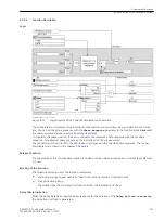
Reviews: