background image

Configuration

5-50

7SA522 Manual

C53000-G1176-C119-2

When using radio clock signals, you must take into account that it can take up to three 
minutes after device start-up or restored reception for the received time signal to be 
decoded. The internal clock is not re-synchronized until then. 

With IRIG B, the year must be set manually, because this standard does not include 
a year value. 

For synchronization using pulses via a binary input, the present device time will ad-
vance to 00 seconds of the next minute for values greater than 30 seconds when the 
positive slope of the pulse arrives. For second values less than 30, the device time will 
be set to 00 seconds of the current minute. Because this signal is not monitored, each 
pulse has a direct effect on the internal clock. 

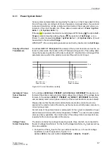
Synchronization 
Offset 

The “Synchronization Offset” (

2IIVHW

) setting allows correlation of the time signal re-

ceived from the radio clock to local time (time zone). The maximum settable offset is 
± 23 h 59 min = ±1439 min. 

Annunciation due 
to missing syn-
chronization

The tolerance time (

(UURU7LPH

 / 

)DXOWLQGLFDWLRQDIWHU

) for time synchroni-

zation fault indicates how long cyclical synchronization may be absent until an alarm 
is given. 

External or internal synchronization normally occurs every minute. The setting for the 
tolerance time must, therefore, always be at least two minutes. Under poor radio clock 
reception conditions, you may delay the trigger of the “error” status condition even 
longer. 

Changing the Syn-
chronization Mode 

When changing synchronization mode, the hardware will change over to the new 
source within one second. This causes breakdown of cyclical synchronization, and the 
internal clock will be disrupted — as at start-up — until the new synchronization 
source takes over. 

After modification to the synchronization offset in the time signal/operating mode, or 
when changing year in IRIG B, the cyclical synchronization is not lost, but there is a 
jump. To call attention to this, the time value causing a jump is reported with “

7LPH

LQWHUUXSWLRQ21

” — without the synchronization offset, and subsequently with 

7LPHLQWHUUXSWLRQ2))

” — with the synchronization offset. 

Operating Messag-
es from the Timing 
System 

After the “

7LPHLQWHUUXSWLRQ21

” message, the you must take into account that 

the clock will jump. This message is issued under the following circumstances: 

if a synchronization interruption lasts longer than the tolerance time interval men-
tioned above, or as mentioned above, if the synchronization mode is changed; 

if a time jump is anticipated. The message itself is stamped with the old time. 

The message “

7LPHLQWHUUXSWLRQ2))

” is triggered: 

when the synchronization is re-established (e.g., after a break in reception by the 
radio clock); 

immediately after a time jump. This message is stamped with the new time after the 
jump, thus allowing determination of the jump interval. 

Time Format 

The time display may be set using either the European format (DD.MM.YYYY) or the 
US format (MM/DD/YYYY). 

n


Summary of Contents for siprotec 7SA522

Page 1: ...2 Distance Protection Manual QWURGXFWLRQ 1 DUGZDUH DQG RQQHFWLRQV 2 QLWLDO QVSHFWLRQV 3 6 3527 HYLFHV 4 RQILJXUDWLRQ 5 XQFWLRQV 6 RQWURO XULQJ 2SHUDWLRQ 7 QVWDOODWLRQ DQG RPPLVVLRQLQJ 8 5RXWLQH KHFNV DQG 0DLQWHQDQFH 9 7HFKQLFDO DWD 10 SSHQGL A SSHQGL B ...

Page 2: ...dicating different degrees of dan ger Warning means that death severe injury or substantial property damage may occur if the appropri ate safety measures are not taken Caution means that minor injury or property damage may occur if the appropriate safety measures are not taken Qualified Personnel Commissioning and operation of the equipment module device described in this manual must be performed ...

Page 3: ...l facilities and personnel of electrical facilities and power plants Applicability of This Manual This manual is valid for SIPROTEC 4 7SA522 Distance Protection firmware version 4 3 Indication of Conformity This product complies with the directive of the Council of the European Communities on the approximation of the laws of the member states relating to electromagnetic compatibility EMC Council D...

Page 4: ...ment Instruction is an important piece of information regarding the product or the part of the manual that deserves special attention QUALIFIED PERSONNEL IND CONT EQ TYPE 1 69CA IND CONT EQ TYPE 1 69CA Warning During operation of electrical equipment certain parts of these devices are under high voltage Severe personal injury or significant equipment damage could result from im proper behavior Onl...

Page 5: ...lection menus 3DUDPHWHU FRQGLWLRQV or possible settings of parameters that appear in the de vice display or on the screen of a PC with DIGSI 4 are additionally shown in italic style This also applies to selection items for selection menus QQXQFLDWLRQV or identifiers for information produced by the device or required by other devices or from the switch gear is shown in mono script same point size a...

Page 6: ...technical improvements without notice Copyright Copyright Siemens AG 2000 All rights reserved Dissemination or reproduction of this document or evaluation and com munication of its contents is not authorized except where expressly per mitted Violations are liable for damages All rights reserved particularly for the purposes of patent application or trademark registration Registered trademarks SIPR...

Page 7: ...g Cubicle Mounting 2 2 2 1 1 Housing 2 2 2 1 2 Screw terminal connections 2 6 2 1 3 Connections to Plug In Terminals 2 10 2 1 4 Connections to Optical Communication Interfaces 2 13 2 1 5 Connections to Electrical Communication Interfaces 2 14 2 2 Version of 7SA522 for Panel Surface Mounting 2 15 2 2 1 Housing 2 15 2 2 2 Screw terminal connections 2 18 2 2 3 Connections to Optical Communication Int...

Page 8: ... Communication 4 3 4 1 3 Settings 4 4 4 1 4 Operations 4 4 4 1 5 Oscillographic Fault Records 4 4 4 2 Operator Control Facilities 4 5 4 2 1 Operator Control Panel On Device 4 5 4 2 2 DIGSI 4 Tool 4 7 4 3 Information Retrieval 4 8 4 3 1 Annunciations 4 9 4 3 2 Measurements 4 11 4 3 3 Oscillographic Fault Records 4 13 4 4 Control 4 14 4 5 Manual Overwrite Tagging 4 16 4 6 General about the Setting P...

Page 9: ... 5 2 1 Preparation 5 7 5 2 2 Structure and Operation of the Configuration Matrix 5 8 5 2 3 Control Commands for switching devices 5 12 5 2 4 Establishing Information Properties 5 14 5 2 5 Performing Configuration 5 21 5 2 5 1 Preset Configurations 5 27 5 2 6 Transferring Metering Values 5 30 5 2 7 Settings for Contact Chatter Blocking 5 32 5 3 Creating User Defined Functions with CFC 5 34 5 4 Esta...

Page 10: ... Settings 6 39 6 2 2 3 Settings 6 41 6 2 2 4 Information Overview 6 42 6 2 3 Distance Protection with Polygonal Tripping Characteristic 6 45 6 2 3 1 Method of Operation 6 45 6 2 3 2 Applying the Function Parameter Settings 6 50 6 2 4 Distance Protection with MHO Characteristic 6 57 6 2 4 1 Method of Operation 6 57 6 2 4 2 Applying the Function Parameter Settings 6 61 6 2 4 3 Settings 6 65 6 2 5 Tr...

Page 11: ...Function Parameter Settings 6 92 6 4 3 Settings 6 95 6 4 4 Information Overview 6 95 6 5 Earth Fault Protection in Earthed Systems 6 97 6 5 1 Method of Operation 6 97 6 5 2 Applying the Function Parameter Settings 6 103 6 5 3 Settings 6 109 6 5 4 Information Overview 6 112 6 6 Earth Fault Protection Teleprotection Schemes 6 113 6 6 1 Method of Operation 6 114 6 6 1 1 Directional Comparison Scheme ...

Page 12: ... 6 8 4 Information Overview 6 131 6 9 Overcurrent Protection 6 132 6 9 1 Method of Operation 6 133 6 9 2 Applying the Function Parameter Settings 6 139 6 9 3 Settings 6 146 6 9 4 Information Overview 6 147 6 10 High Current Switch On To Fault Protection 6 149 6 10 1 Method of Operation 6 149 6 10 2 Applying the Function Parameter Settings 6 150 6 10 3 Settings 6 150 6 10 4 Information Overview 6 1...

Page 13: ...ion Overview 6 194 6 14 Fault Location 6 195 6 14 1 Method of Operation 6 195 6 14 2 Applying the Function Parameter Setting 6 197 6 14 3 Settings 6 198 6 14 4 Information Overview 6 198 6 15 Circuit Breaker Failure Protection 6 200 6 15 1 Method of Operation 6 200 6 15 2 Applying the Function Parameter Settings 6 211 6 15 3 Settings 6 214 6 15 4 Information Overview 6 214 6 16 Monitoring Function...

Page 14: ...Circuit Breaker Trip Test 6 242 6 17 6 Setting Parameters 6 243 6 17 7 Settings 6 244 6 17 8 Information Overview 6 245 6 18 Supplementary Functions 6 246 6 18 1 Processing of Messages 6 246 6 18 2 Operational Measurement and Energy Metering 6 247 6 18 3 Data Storage for Fault Recording 6 249 6 18 4 Applying the Function Parameter Settings 6 249 6 18 5 Settings 6 250 6 18 6 Information Overview 6 ...

Page 15: ...e Switching Statistics 7 11 7 1 2 2 Resetting and Setting the Switching Statistics 7 12 7 1 3 Measured Values 7 13 7 1 3 1 Measured Values 7 13 7 1 3 2 Setting and Retrieval of User Defined Set points 7 17 7 1 3 3 Retrieval and Resetting of User Defined Pulse Metered Values PMV 7 19 7 1 4 Fault Records 7 20 7 1 4 1 Viewing Fault Records 7 20 7 1 4 2 Saving the Fault Records 7 21 7 2 Control of Dev...

Page 16: ...allation 8 2 8 1 2 Termination variants 8 6 8 1 3 Hardware Modifications 8 11 8 1 3 1 General 8 11 8 1 3 2 Jumpers on the Printed Circuit Boards 8 12 8 2 Checking the Connections 8 20 8 2 1 Data Connections 8 20 8 2 2 Power Plant Connections 8 22 8 3 Commissioning 8 24 8 3 1 Current Voltage and Phase Rotation Checks 8 25 8 3 2 Directional Checks with Load Current 8 26 8 3 3 Polarity check for the ...

Page 17: ...37 8 3 7 Checking the Binary Inputs and Outputs 8 38 8 3 8 Tests for the Circuit Breaker Failure Protection 8 40 8 3 9 Testing User Defined Functions 8 42 8 3 10 Trip and Close Test with the Circuit Breaker 8 42 8 3 11 Triggering Oscillographic Recordings 8 43 8 3 12 Generate Indications 8 44 8 4 Final Preparation of the Device 8 46 9 Routine Checks and Maintenance 9 1 9 1 General 9 2 9 2 Routine ...

Page 18: ...stance Protection 10 10 10 3 Power Swing Supplement 10 12 10 4 Distance Protection Teleprotection Schemes 10 13 10 5 Earth Fault Protection in Earthed Systems 10 14 10 6 Earth Fault Protection Teleprotection Schemes 10 20 10 7 Weak Infeed Tripping 10 20 10 8 External Direct and Remote Tripping 10 20 10 9 Overcurrent Protection 10 21 10 10 High Current Switch On To Fault Protection 10 23 10 11 Auto...

Page 19: ...Ordering Information and Accessories A 2 1 1 1 Accessories A 4 1 2 General Diagrams A 6 1 2 1 Panel Flush Mounting or Cubicle Mounting A 6 1 2 2 Panel Surface Mounting A 9 1 3 Connection Examples A 14 1 4 Preset Configurations A 21 1 5 Protocol Dependent Functions A 24 B Appendix B 1 2 1 Settings B 2 2 2 List of Information B 18 2 3 Measured Values B 47 Index Index i ...

Page 20: ...7SA522 Manual C53000 G1176 C119 2 ...

Page 21: ...1 The SIPROTEC 4 devices 7SA522 are introduced in this chapter An overview of the devices is presented in their application characteristics and scope of functions 1 1 Overall Operation 1 2 1 2 Applications 1 4 1 3 Features 1 6 1 4 Scope of Functions 1 7 ...

Page 22: ...sidual current from the current transformer star point the earth current of a parallel line for parallel line compensation or the star point current of a power transformer for earth fault direction determination A voltage measuring input is provided for each phase earth voltage A further voltage input U4 may optionally be used to measure either the displacement voltage e n voltage or any other vol...

Page 23: ...itions Front Elements Light emitting diodes LEDs and a display screen LCD on the front panel provide information such as targets measured values messages related to events or faults status and functional status of the 7SA522 Integrated control and numeric keys in conjunction with the LCD facilitate local inter action with the 7SA522 All information of the device can be accessed using the inte grat...

Page 24: ...e located along the entire line length it is possible to achieve a non delayed trip sig nal In the event of a failure of the measured voltages due to a fault in the secondary cir cuits e g trip of the voltage transformer mcb or a fuse the device can automatically revert to an emergency operation with an integrated time delayed overcurrent protec tion until the measured voltage again becomes availa...

Page 25: ...d are subsequently avail able for fault analysis Communication Serial interfaces are available for communications with PCs RTUs and SCADA sys tems A 9 pin D subminiature female connector on the front panel is used for local commu nications with a personal computer DIGSI 4 software is required to communicate via this port Using the DIGSI 4 software settings and configuration can be made to the rela...

Page 26: ...for earth faults or MHO circle characteristic Direction determination with polygon or polarization with MHO circle is done with unfaulted loop quadrature voltages and voltage memory thereby achieving unlimited directional sensitivity Compensation of the influence of a parallel line during earth faults is possible Abundance of additional protective and control functions available some as op tions C...

Page 27: ...tion with MHO circle is done with unfaulted loop quadrature voltages and voltage memory thereby achieving unlimited directional sensitivity and not affected by capacitive voltage transformer transients current transformer saturation detection and compensation compensation against the influence of a parallel line is possible shortest tripping time is approx 15 ms fN 60 Hz or 17 ms fN 50 Hz phase se...

Page 28: ... delayed tripping after switch on to fault with any stage is possible Tripping Echo at Line Ends with No or Weak Infeed possible in conjunction with teleprotection schemes allows fast tripping at both line ends even if there is no or only weak infeed available at one line end phase segregated tripping is possible External Direct and Remote Tripping tripping at the local line end from an external d...

Page 29: ...onditions with advance calculation of the synchro time possible adjustable minimum and maximum voltage check synchronism or dead line dead bus also before manual closure of the circuit breaker possible with separate limit values measurement via transformer also possible measuring voltages optionally phase phase or phase earth Overvoltage Protection optional Overvoltage detection of each phase eart...

Page 30: ...ence Monitoring of the battery Further Functions Battery buffered real time clock which may be sychronized via a syn chronization signal DCF77 IRIG B via satellite receiver binary input or system interface fault event memory for the last 8 network faults faults in the power system with real time stamps ms resolution fault recording memory and data transfer for analogue and user con figurable binar...

Page 31: ...of the 7SA522 The different housing versions and available termination techniques are described The recommended and permitted data for the wiring is stated and suitable accessories and tools are given 2 1 Version of 7SA522 for Panel Flush Mounting Cubicle Mounting 2 2 2 2 Version of 7SA522 for Panel Surface Mounting 2 15 ...

Page 32: ...sponding plug connectors The rear plate screwed to the tube contains the required connectors for the external connections to the device The front cover can be detached after removal of the covers located on the 4 corners of the front cover and the 4 screws that are then revealed Housing size 1 1 has 2 ad ditional screw covers located at the centre of the top and bottom of the front cover frame acc...

Page 33: ... escape from specific menues or execute changes such as setting changes 5 Numerical keys These keys serve for entry of numerical values such as limit value settings 6 Function keys Four function keys allow the quick and simple execution of frequently used ac tions Typical applications include for example jumping to a particular position in the menu tree such as the fault data in the Trip Log or th...

Page 34: ... Next to the LEDs on the front panel a labeling strip is provided on which the user specified LED functions may be written 10 Operating condition indicators The two LEDs RUN green and ERROR red indicate the operating condition of the device 11 Coverings for the screws that secure the front panel View of Front Panel Housing Size 1 1 The significance of the operating and display elements is the same...

Page 35: ...ew type termi nals Figure 2 4 Rear view of a 7SA522 housing size 1 1 terminal arrangement example only 1 2 3 4 5 6 7 8 1 2 3 4 5 6 7 8 9 10 11 12 13 14 15 16 17 18 A B C K J 1 2 3 4 5 6 7 8 9 10 11 12 13 14 15 16 17 18 R Q 1 2 3 4 5 6 7 8 9 10 11 12 Ch1 Ch2 Ch1 Ch2 Ch1 Ch2 D E P Slave P Master RS232 RS485 1 2 3 4 5 6 7 8 9 10 11 12 13 14 15 16 17 18 1 2 3 4 5 6 7 8 9 10 11 12 13 14 15 16 17 18 Ch1...

Page 36: ...ion terminal modules are available in 2 variants Figure 2 5 Figure 2 5 Connection plug module with screw terminals for voltage connections rear view Figure 2 6 shows an example of the allocation of an individual screw terminal to its ter minal number Figure 2 6 Allocation of screw terminal to terminal number example Terminal Block for Current Connections There is one version of a terminal block fo...

Page 37: ...inserted into the case the short circuits of the current paths are removed after the transformers of the device are connected to the terminal pairs The short circuit feature of the relay is an important and reliable safety feature how ever the feature does not relieve the user from exercising proper care when working with current transformer secondary circuits Connections to Voltage Terminals Ring...

Page 38: ...uring terminals can be included in the short circuit On each terminal it is possible to connect two short circuiting links or one short circuit link and one lug or one individual conductor The links meet the safety requirements for protection against electric shock There are two types of links one for voltage connections and one for current connec tions The links are illustrated in Figure 2 8 Orde...

Page 39: ...information is provided in Section 1 1 in the Appendix Figure 2 9 Covering caps for terminal blocks with screw terminals Covering cap for 18 terminal voltage Covering cap for 12 terminal voltage connection terminal block or 8 Terminal Current connection terminal block SIEMENS C73334 A1 C31 1 PCGF AMP SIEMENS C73334 A1 C32 1 PCGF AMP ...

Page 40: ... and connection numbers letters Each plug in terminal forms a complete set of connections that consists of three pins arranged as follows Pin a Signal connection Pin b Common connection Pin c Shielding connection The signal pins are the only terminal pins that are directly connected to the internal printed circuit boards of the 7SA522 Depending on the version of the terminal block 18 or 12 signal ...

Page 41: ...pins are also connected to the housing Depending on the version of the terminal block 18 or 12 shielding connections are provided Figure 2 12 Schematic diagram of the plug in terminal blocks Connections to Plug In Terminals Connections to plug in terminals are made with pin connectors There are two versions of pin connectors Version 1 2 pin connector Version 2 3 pin connector Signal connection Com...

Page 42: ... diameter of the conductor being used Section 0 5 mm2 to 1 0 mm2 e g Bandware 4000 pieces type 827039 1 from AMP Corp Individual piece type 827396 1 from AMP Corp Section 1 0 mm2 to 2 5 mm2 e g Bandware 4000 pieces type 827040 1 from AMP Corp Individual piece type 827397 1 from AMP Corp Connection of a conductor to a contact is performed using a hand crimping tool e g type 0 825582 from Corp AMP A...

Page 43: ...removed by turning them 90 to the left Figure 2 14 Optical communication interfaces with protective caps Connections to Optical Communication Interfaces Optical connector type ST connector Fibre type Multimode graded index G optical fibre G50 125 µm G62 5 125 µm G100 140 µm Wavelength λ 820 nm approximately Allowable bending radius For indoor cable rmin 5 cm 2 in For outdoor cable rmin 20 cm 8 in ...

Page 44: ...n be used The necessary communication cables are dependent on the type of interface RS232 EIA232 Five wire twisted and shielded e g interface cable 7XV5100 4 RS485 EIA485 Three wire twisted and shielded Profibus Two wire or four wire twisted and shielded Wire type A DIN 19245 part 2 and EN 50170 vol 2 twisted and shielded Wire Resistance 135 Ω to 165 Ω f 100 kHz Capacitance 30 nF km 48 nF mile Cir...

Page 45: ... the insertion of the modules are mounted on the inside of the rectangular tube Connections between the modules and from the modules to the front cover are established with flat ribbon cables and corresponding plug connectors The front cover can be detached after removal of the covers located on the 4 corners of the front cover and the 4 screws that are then revealed Housing size 1 1 has 2 ad diti...

Page 46: ...ific menues or execute changes such as setting changes 5 Numerical keys These keys serve for entry of numerical values such as limit value settings 6 Function keys Four function keys allow the quick and simple execution of frequently used ac tions Typical applications include for example jumping to a particular position in the menu tree such as the fault data in the Trip Log or the measured values...

Page 47: ... of the device 11 Coverings for the screws that secure the front panel View of Front Panel Housing Size1 1 The significance of the operating and display elements is the same as explained after Figure 2 16 Figure 2 17 Front view of a 7SA522 housing size 1 1 for panel surface mounting without optical connections 77 78 79 80 81 82 83 84 85 76 52 53 54 55 56 57 58 59 60 62 63 64 65 66 72 67 68 69 70 7...

Page 48: ... in 2 2 3 Connections to Optical Communication Interfaces Optical Communication Interfaces Optical communication interfaces may be 1 to 4 channel The ports are supplied with caps to protect the optical components against dust or other contaminants The caps can be removed by turning them 90 to the left A maximum of two fibre optic channels are located in each inclined housing In the case of device ...

Page 49: ...ng the available channel designations B to E is printed onto the inclined housing In Figure 2 19 the channels B and C are fitted Figure 2 19 Inclined housing with fibre optic connections example channel B and C fitted Housing for optical communication interfaces channel D and E Housing for optical communication interfaces channel B and C Channel B Channel D Channel C Channel E ...

Page 50: ...rofibus interface has a DSUB socket instead of the fibre optic channel B in the inclined housing located on the bottom side of the device see Figure 2 20 Figure 2 20 Inclined housing with fibre optic connection and DSUB socket for Profibus inter face n Channel B Channel D Channel C Channel E ...

Page 51: ...ting menus of the device us ing the operator control panel on the front of the device and the operator control win dows in DIGSI 4 For personnel inexperienced with the 7SA522 these checks also provide a quick and simple method for understanding the operation of the control pan el and DIGSI 4 The electrical tests can be done without measuring quantities being applied Observations relevant to long t...

Page 52: ...nce booklet and all notes and hints that are en closed in the packaging The transport packaging can be reused in the same manner for further transport Stor age packaging alone for the individual devices is not sufficient for transport If alter native packaging is used shock requirements according to IEC 60255 21 1 Class 2 and IEC 60255 21 2 Class 1 must be met The device should be in the final ope...

Page 53: ...e has been in the operating area for at least two hours This time period allows the device to attain temperature equilibrium and prevents dampness and con densation from occurring Power Up For a first electrical inspection of the device it is sufficient to ensure safe grounding of the housing and to apply the power supply voltage o Connect the ground of the device solidly to the ground of the loca...

Page 54: ...s the start up messages must vanish from the display in which the complete ordering number the version of firmware implemented and the factory number are shown and the default display must appear Depending on the assignment of the LEDs some indicators may light up during and after power up ...

Page 55: ... the complete ordering number of the device the version of firmware imple mented and the serial number q When the device is ready for operation first press the key The 0 1 0 18 ap pears q Using the key select the menu item 6HWWLQJV and move to the device settings using the key The 6 77 1 6 menu appears as shown in Figure 3 1 q Using the key select the menu item 6HWXS WUDV and switch to the selecti...

Page 56: ... key The 1181 7 21 sub menu appears q Using the key select the menu item YHQW RJ and move to the 9 17 2 sub menu using the key The last number in the upper right corner of the display indicates the number of oper ational messages stored in memory The number before the slash indicates the mes sage presently being displayed Upon entering the menu the latest newest message is shown The date and time ...

Page 57: ...select the menu item 6HWXS WUDV and switch to the selection 6 783 75 6 using the key See Figure 3 3 q Using the key select the sub menu item RQWUDVW q If a change of the contrast of the integrated LCD is desired press the key En ter now the password 000000 default The existing setting appears in a frame with a blinking cursor q Overwrite the present setting with the desired setting using the numer...

Page 58: ...bed below To perform the steps in the examples first connect the SIPROTEC 4 device to the PC and match the DIGSI 4 interface data with the equip ment To accomplish this q Establish a physical connection between a serial interface of the PC and the oper ating serial interface of the device on the front panel q Open the DIGSI 4 application in the PC q Generate a new project by clicking on LOH 1HZ in...

Page 59: ...d reads the settings needed for communication transfer format transfer speed through the interface Figure 3 6 Plug Play dialogue box for communication between device and PC A direct connection is then established on line the data are exchanged between the PC and the device and the initial screen for DIGSI 4 opens as shown on Figure 3 7 q By double clicking 2QOLQH in the navigation window left wind...

Page 60: ...GDU q The present date and time are shown in the data window right as illustrated in Fig ure 3 8 q Double click on this entry in the data window Figure 3 8 DIGSI 4 Viewing the secondary operating measured values example A table of the secondary operating measured values appears as shown in Figure 3 9 Since no measured AC currents or voltages are present at this time all operating measured values a...

Page 61: ...he number designation for an event is provided with a description of the mes sage The corresponding cause value ON or OFF and date and time of the event are given The events are listed chronologically the newest message is shown first Figure 3 10 DIGSI 4 Operational messages window example q Press the key on the device all LEDs should light while the key is pressed q The message Reset LED appears ...

Page 62: ...ld shows the present date and the approximate present time according to the device The day of the week is automatically derived from the date and cannot be edited Edit the input fields DWH and 7LPH The format depends on your regional settings of the PC See Figure 3 12 Date mm dd yyyy or dd mm yyyyy Time hh mm ss Click 2 to download the entered values to the device The former values are changed and...

Page 63: ...y must not lead to condensation or ice buildup After extended storage the power supply of the device should be energized approx imately every two years for one or two days to regenerate the electrolytic capacitors in the power supply This procedure should also be done prior to the device being put in service Under extreme climatic conditions tropics pre warming is achieved at the same time and con...

Page 64: ...7SA522 Manual C53000 G1176 C119 2 ...

Page 65: ... specific device some of the functions discussed may not be available Details about the extent of the functions of the devices the individual settings and the representation structure of the system data are found in the following chapters and the DIGSI 4 instruction book 4 1 General 4 2 4 2 Operator Control Facilities 4 5 4 3 Information Retrieval 4 8 4 4 Control 4 14 4 5 Manual Overwrite Tagging ...

Page 66: ...ed values ensure the highest security in establishing the devic es correct responses Device errors are recognized and quickly annunciated by inte grated self monitoring routines Failure of protection during a fault is therefore almost entirely prevented You may choose devices with separate protective and process control functions or select a solution that implements both requirements The following...

Page 67: ...f feeder devices in the SICAM substation control system example In the sample configuration in Figure 4 1 data transmitted from the feeder devices can be processed in the sub station control device SICAM SC displayed at the operating and observation station SICAM WinCC and transferred by the remote terminal unit interfaces via the network channels to network control centres SCADA In the case when ...

Page 68: ...IGSI 4 Exam ples of operations are switching retrieval of information or changing of setting groups These operations can also be performed using the operator control panel on the front of the SIPROTEC 4 device 4 1 5 Oscillographic Fault Records DIGSI 4 can also be used to retrieve oscillographic fault data captured by the SIPROTEC 4 device The DIGRA 4 software program can then be used to provide s...

Page 69: ...l with Four Line Display Figure 4 2 SIPROTEC 4 Device operator control panel with four line display examples Note Refer to Chapter 2 to determine the type of operating field for your specific SIPROTEC 4 device SIEMENS SIPROTEC 1 2 6 3 0 5 4 7 8 9 7SA522 RUN ERROR MENU ESC LED ENTER F4 F1 F2 F3 Event Log Operation MAIN MENU 01 05 Annunciation 1 Measurement 2 SIEMENS SIPROTEC 1 2 6 3 0 5 4 7 8 9 7SA...

Page 70: ... device and movement within the op erator control display are accomplished with the keys q The main menu is opened with the key q Changes are cancelled or confirmed with the and keys respectively q Numerical values are entered with the to keys the key for a decimal point and the key for a negative sign If a value of infinity is desired press the decimal point key twice appears in the display q The...

Page 71: ...lso selected in this matrix The setting options are presented in an easy to read tabular format Parts of the matrix can be minimized or expanded as desired to simplify the displayed sections and therefore the setting process Filter functions can reduce the size of the matrix to display only relevant information Passwords Password entry is required for tasks such as changing settings executing cont...

Page 72: ...bstation control system then information transfer can take place via a connection to the system interface of the SIPROTEC 4 device to q higher level control systems or q substation control devices e g SICAM SC Local On site the operator control panel of the SIPROTEC 4 device can be used to retrieve information DIGSI 4 Information retrieval is simple and fast when DIGSI 4 is used For local use conn...

Page 73: ...ssages about switching operations or monitoring functions q Trip Log Fault messages q General interrogation display of present condition messages q Spontaneous messages continuous display of important messages from the de vice e g after faults switching operations etc k451 gif Figure 4 3 DIGSI 4 annunciations example Display in DIGSI 4 To view the indications in DIGSI 4 2QOLQH Select QQXQFLDWLRQ i...

Page 74: ...EC 4 device Select 0DLQ 0HQX QQXQFLDWLRQ e g YHQW RJ or 7ULS RJ Figure 4 4 SIPROTEC 4 device display of operating messages in the event log ex ample Figure 4 5 SIPROTEC 4 device display of fault messages example 1181 7 21 YHQW RJ 7ULS RJ 0 1 0 18 QQXQFLDWLRQ 0HDVXUHPHQW 9 17 2 5HVHW 21 75 3 2 DVW DXOW QG DVW DXOW 67 8 7 1HWZRUN DXOW 21 ...

Page 75: ...as ured values q Percentage values relative to nominal ratings q Other values calculated by the device e g thermal values or user defined values q Statistics values k452 gif Figure 4 6 DIGSI 4 measured value display example Display in DIGSI 4 To display the measured values in the DIGSI 4 2QOLQH Select 0HDVXUHPHQW in the navigation left window The measured value groups appear in the data right wind...

Page 76: ...easured values example 0 685 0 17 2SHUDWLRQ SUL 2SHUDWLRQ VHF 0 1 0 18 QQXQFLDWLRQ 0HDVXUHPHQW 0 685 0 17 2SHUDWLRQ SUL 2SHUDWLRQ VHF 23 5 7 21 35 Note Measured values can also be displayed in the default display and the control display Prior to this the measured values to be indicated have to be configured in the config uration matrix under settings in DIGSI 4 Then their position within the LCD d...

Page 77: ...program is used to convert the oscillographic data into graphical rep resentations that can be used to analyse the fault or the event captured by the device DIGRA 4 calculates additional values from the waveform data e g impedances and rms values and displays the captured and calculated values in q analogue curves with timebase time signals q phasor diagrams q locus diagrams and q harmonic graphs ...

Page 78: ...ation control devices such as SICAM SC Local On site the SIPROTEC 4 device offers the possibility to control a circuit breaker or primary switching equipment using the operator control panel For devices with a four line display switching operations are controlled using 0DLQ PHQX RQWURO UHDNHU 6ZLWFK RQWURO Equipment and in tended direction 21 or 2 Figure 4 9 or The Function Keys F1 to F4 The funct...

Page 79: ...cally supported design tool CFC for logic functions in DIGSI 4 infor mation can be logically combined Command outputs can be derived from the output of logic functions The link of the output of the CFC functions to the respective device outputs is determined in the configuration matrix Passwords Only authorized personnel can perform switching operations Switching operations are protected by passwo...

Page 80: ...hort period without disconnecting the wires This function is activated using the op erator control panel 0DLQ 0HQX RQWURO UHDNHU 6ZLWFK 6HW 6WDWXV Tagging To identify unusual operating conditions in the power system tagging can be done The tagging can for example be entered as additional operating conditions in inter locking checks which are set up with CFC Tagging is configured in the same way as...

Page 81: ...ffers system port etc I O configu ration q defining user definable logic functions CFC q Specific Settings q settings for all elements to be used q settings of the protective functions q settings of the process control functions Settings are first done Off line The settings are then loaded into the SIPROTEC 4 device on site using the operating serial interface or remotely by modem and the service ...

Page 82: ...asswords Setting steps partially build on the decisions from the previous steps By following the sequence listed unnecessary changes and rework are avoided The sequence en sures that information required for an individual step will be available To design the control display for example the physical connections between the de vice and the primary equipment must be known These connections are determ...

Page 83: ...anel but not changed Display the settings on the LCD using 0DLQ 0HQX 6HWWLQJV e g 0DVNLQJ 2 Change settings such as date and time using 0DLQ 0HQX 6HWWLQJV 6HWXS WUDV Figure 4 14 Changing settings using the operator control panel example 0 1 0 18 QQXQFLDWLRQ 0HDVXUHPHQW RQWURO 6HWWLQJV 7HVW LDJQRVH 6 77 1 6 HYLFH RQILJ 0DVNLQJ 2 3 6 VWHP DWD URXS URXS URXS URXS KDQJH URXS 2VF DXOW 5HF 6HWXS WUDV HY...

Page 84: ...and disabling in the Device Configuration area of the settings To specify the active functions using DIGSI 4 Double click on HYLFH RQILJXUDWLRQ in the data window Click on the individual fields and select the functions to be enabled k453 gif Figure 4 15 DIGSI 4 setting the device configuration example The device configuration can be viewed from the operator control panel on the SIPROTEC 4 device I...

Page 85: ... programmable keys on the operating field e g assigned switching operations etc as the origin of the information q CFC C programmable logic user specific logic outputs as the origin of the infor mation q Destination of the information with q binary outputs for the output of signals q LED display of information on the device front e g messages q system interface S transmission of information e g to...

Page 86: ...n from view so that you can view only the sections of the total matrix that are relevant New Information A further function of the configuration matrix is the capability to define new information This is accomplished by inserting a new line defining the appropriate information type and assigning it to a source and a destination The new information can also be dis played in the LCD of the SIPROTEC ...

Page 87: ...c logic s inputs e g the individual messages that are to be combined to form a grouped message must be marked in the Destination C column The logic s output the grouped message in this example is derived from the Source C column Viewing the Config uration on the Operating Panel The configuration can be seen on the operating panel of the SIPROTEC 4 device In the main menu select 6HWWLQJV 0DVNLQJ 2 ...

Page 88: ...les that are specially created for the requirements of process control engineering e g MAX MIN etc are available The CFC modules are combined to form complete CFC logic functions in order to q perform system specific checks e g interlocking q generate messages if measured values approach a critical value or q build group messages for transfer to a substation control systems k4122 gif Figure 4 19 D...

Page 89: ...SIPROTEC 4 Devices 4 25 7SA522 Manual C53000 G1176 C119 2 Figure 4 20 CFC Logic example ...

Page 90: ...a such as frequency voltage etc q data for the main current transformers and voltage transformers q circuit breaker or primary switch gear information k4124 gif Figure 4 21 DIGSI 4 setting the power system data example Power System Data 2 Power System Data 2 are part of the setting groups which can be switched over dur ing operation see chapter 4 11 These include for example q Primary Operating Vo...

Page 91: ...tection and control for the existing configuration of the net work being protected In other words the protection and control can be changed as the network changes The setting groups are saved in the device The setting groups can be changed during operation using DIGSI 4 from the operator control panel on the device by triggering binary inputs or via the system interface k4114 gif Figure 4 22 DIGSI...

Page 92: ...re 4 23 DIGSI 4 entering settings for a protective function example Changing Setting Groups The setting groups can be changed during operation using DIGSI 4 from the opera tor control panel on the device by triggering binary inputs or via the system interface The active setting group is indicated Figure 4 24 SIPROTEC 4 device changing setting groups on the operator control panel 1 5283 7 9 5283 UR...

Page 93: ...on of network faults on the LEDs and the LCD on the front of the SIPROTEC 4 device are defined in the DIGSI 4 window shown in Figure 4 25 k4123 gif Figure 4 25 DIGSI 4 general device settings targets example The setting can also be changed at any time using the operator control panel on the SIPROTEC 4 device 0DLQ 0HQX 6HWWLQJV HYLFH ...

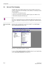
Page 94: ...re connected via a 9 pin D subminiature port on the back panel of the device Setting of the time synchronization is done exclusively with DIGSI 4 Double click on 7LPH 6 QFKURQL DWLRQ in the data window and enter the set tings ka455 gif Figure 4 26 DIGSI 4 setting of the time synchronization example Read out on the Operator Control Panel Using the SIPROTEC 4 device operator control panel the time s...

Page 95: ...GSI 4 via modem and or a star connection All DIGSI 4 operations are possible via this interface q The system interface on the back panel of the device is used for connection to a central master control system such as SICAM SC q The time control interface on the back panel of the device is used for time synchro nization e g IRIG B DCF77 In the DIGSI 4 interface settings window under Serial Ports th...

Page 96: ...e interface settings can be checked using the SIPROTEC 4 device operator con trol panel In the main menu select 6HWWLQJV 6HWXS WUDV 6HULDO 3RUWV follow ing menus Figure 4 29 Read out of serial interface settings from the operator control panel example 6 5 32576 URQW 3RUW 6 VWHP 3RUW 6HUYLFH 3RUW 6 783 75 6 DWH 7LPH ORFN 6HWXS 6HULDO 3RUWV HYLFH 0 9HUVLRQ RQWUDVW Note The serial interface for conne...

Page 97: ...ardware test menus q Individual settings q Setting Groups ka458 gif Figure 4 30 DIGSI 4 window indicating the active passwords example When using DIGSI 4 or the operator control panel on the SIPROTEC 4 device a password is requested for the specific functions Note Password protection against unauthorized access is only in place during on line op eration The passwords for setting changes are first ...

Page 98: ...assword and confirm with the new password again and 2 k4119 gif Figure 4 31 DIGSI 4 changing passwords Passwords are numbers up to 8 digits At delivery all passwords are set to 000000 n Note If the password for setting group switching has been forgotten a temporary password can be received from Siemens The temporary password can be used to define a new password for this function The registration n...

Page 99: ...a which outputs Which user definable functions need to be performed in CFC Continuous Function Chart Which information should be displayed on the front panel of the device Which interfaces are to be used Which time source is to be used to synchronize the internal clock This chapter describes in details how to configure the 7SA522 5 1 Configuration of Functions 5 2 5 2 Configuration of the Binary I...

Page 100: ...522 There are no messages and corresponding settings functions limit values are not displayed dur ing detailed settings Determination of Functional Scope Configuration settings may be entered using a PC and the software program DIGSI 4 and transferred via the operating interface on the device front or via the rear serial service interface Operation via DIGSI 4 is described in Chapter 4 as well as ...

Page 101: ... type can be selected for the distance protection dependent on the device version In setting address the selection for the phase phase measuring systems 3KDVH LVWDQFH is done and in address the selection for the phase earth measuring systems DUWK LVWDQFH is done A selection between a polygonal tripping characteristic 4XDGULODWHUDO and circular MHO characteristic 0 2 is available In Sub sections 6 ...

Page 102: ...r of the automatic reclosure depends on the cycles of the remote end However the number of cycles must be set at least at one end of the line and this end must have a reliable infeed The other end or ends may operate with adaptive dead time See section 6 11 1 for detailed explanations The 5 21752 02 under address allows a total of four options You can determine whether the sequence of automatic re...

Page 103: ...WV 5 1 1 Settings Addr Setting Title Setting Options Default Setting Comments 103 Grp Chge OPTION Disabled Enabled Disabled Setting Group Change Option 110 Trip mode 3pole only 1 3pole 3pole only Trip mode 112 Phase Distance Quadrilateral MHO Disabled Quadrilateral Phase Distance 113 Earth Distance Quadrilateral MHO Disabled Quadrilateral Earth Distance 120 Power Swing Disabled Enabled Disabled Po...

Page 104: ...rol mode Pickup w Tact Pickup w o Tact Trip w Tact Trip w o Tact Pickup w Tact Auto Reclose control mode 135 Synchro Check Disabled Enabled Disabled Synchronism and Voltage Check 137 Overvoltage Disabled Enabled Disabled Overvoltage 138 Fault Locator Disabled Enabled Enabled Fault Locator 139 BREAKER FAILURE Disabled Enabled Disabled Breaker Failure Protection 140 TripCirc Superv Disabled 1 trip c...

Page 105: ... saved if desired prior to changing the configuration 5 2 1 Preparation Before configuration is started the overall interfacing requirements must be assessed The required inputs and outputs must be compared with the number of physical inputs and outputs present on the relay The types of indications and commands and their requirements should be taken into account Indications Indications may be info...

Page 106: ... Configuration of information is performed using a PC and the DIGSI 4 software pro gram via the operator or service interface The configuration is represented in DIGSI 4 as a matrix Figure 5 4 Each row is assigned to an information of the de vice It is identified by a function number No LCD text display text D an explanation long text L minimized in Figure 5 4 and an information type T The columns...

Page 107: ...atched The possible combinations of information and interfaces is dependent on the informa tion type Impossible combinations are filtered out by DIGSI 4 plausibility checks The matrix columns are divided into three types Information Source and Destination To the left of the matrix information is divided into information groups Reducing the Matrix The matrix may become very extensive because of the...

Page 108: ... configuration type is available in an abbreviated form For exam ple the abbreviation H1 in a cell of the common binary input BI column means that the corresponding information is configured with active voltage High to binary input 1 If an information is assigned to several sources or destinations the abbreviations of all destinations are shown separated by commas If there is not enough space in t...

Page 109: ... 3 relays with Single Outputs and Common Output without Feedback CF_D3 Double Command 3 relays with Single Outputs and Common Output with Feedback C_D4 Double Command 4 relays with Double Outputs without Feedback CF_D4 Double Command 4 relays with Double Outputs with Feedback C_D2N Double Command 2 relays with Single Outputs Negated without Feedback CF_D2N Double Command 2 relays with Single Outpu...

Page 110: ...r double commands the first output relay is selected using DIGSI 4 The other out put relays will be automatically selected by DIGSI 4 In the sequence of output relays each TRIP command is placed before the associated CLOSE command For commands with feedback indications DIGSI 4 reserves another line in the configu ration matrix for the switching device feedback indications Here the OPEN position fe...

Page 111: ...e 5 7 Double command with single contacts plus common contact C X C t CLOSE Switching device C L L Matrix configuration 1 CLOSE command CLOSE command C C TRIP command t CLOSE TRIP Switching device C C L L Matrix configuration C X 1 C X 2 CLOSE command C C TRIP command CC t CLOSE TRIP Switching device C C L L CC Matrix configuration C X 1 C X 2 3 X CC ...

Page 112: ...URSHUWLHV can be selected For example if the cursor is positioned on a specific output indication the right mouse button is pressed and the menu item 3URSHUWLHV is selected then a choice of whether the indication should appear in the oscillographic fault records Figures 5 10 5 11 and 5 12 is presented For internal single point indications the default status of the indication on off or undefined af...

Page 113: ...formation type Internal Single Point Indication IntSP Singe Point Indica tion SP Figure 5 12 Information properties example for information type Single Point Indication SP Double Point Indi cation DP In addition to the properties entered for single point indications a Suppress interme diate position check box is available which may be checked to suppress the interme diate indication during operati...

Page 114: ...n is only distributed when the new state continues to exist after a preset time interval in milliseconds The setting range is from 0 to 86 400 000 ms or 24 hours Whether or not the filter interval is restarted for each change of state during the filtering filter re triggering is selectable It is also possible to set chatter suppression for each indication Figure 5 12 and 5 13 The contact chatter s...

Page 115: ... number of positions to be represented Using the display offset the beginning of the evaluated bits may have an offset of a programmed number The stepping of the transfomer taps may be modified using the tap interval feature see example Example Four transformer position settings are to be represented by three binary in puts using the designators 3 through 6 The encoding is binary Using three binar...

Page 116: ...t should be matched to a certain amp value the following values are entered in window according to Figure 5 15 The LPHQVLRQ is A amps The RQYHUVLRQ DFWRU is 150 150 A corresponds to 100 input current The limit value upon start up is set for 120 A Metered Values For metered values the determination of the polarity is determined by the direc tion of power flow Figure 5 16 The user may also define th...

Page 117: ...formation may be deleted at any time in contrast to predefined groups and information In order to insert a new information group click on a cell within a group that is next to the location where the new group should be located After pressing the right mouse button a context menu appears Figure 5 17 Figure 5 17 Dialogue box to insert a new information group If one of the first two alternatives is s...

Page 118: ...DOXHV and RXQWHU 9DOXHV To insert a specific information unit into an information group first select it in the cat alog and using the left mouse button it should then be dragged from the information catalog window to a group area on the left of the matrix After the mouse button is re leased the new information unit is inserted into the proper group In order to change the user defined information d...

Page 119: ...d as the configuration choices In other cases three options will be offered e g latched 8 unlatched and B not allocated Entries resulting in an implausible configuration are blocked and inaccessible to the user Configuring Binary Inputs as Sources Single point indications double point indications and pulse metered values can all be configured as binary inputs In addition whether or not binary inpu...

Page 120: ...IntSP A function key may be occupied because it has already been set as an operating function for the relay As delivered from the factory the device s function keys F1 F2 and F3 are pre config ured In order to configure a new indication select one of the options OPEN CLOSE ON OFF etc from the indication group in the information catalog and drag it to the left side of the matrix Upon release a new ...

Page 121: ... lect latched the output relay remains energized even after the indication is no longer present It must be manually reset by pressing the LED Reset button on the front panel of the device or via a binary input with the indication function 5HVHW or via the serial system interface If unlatched is selected the output relay disengages as soon as the indication disappears Fast Binary Out puts The binar...

Page 122: ...ter means independent of the switching direction an indication is issued during each operation of the switching device For double commands with a common output a fourth alternative Common contact appears Using this the binary output may be defined as the common output common contact When this is the case several double commands with common contacts may be assigned to the same common output common ...

Page 123: ...s being conducted a second one cannot be performed Switching Authority Local Commands A local control switching command is only allowed if local control is enabled on the relay via lockswitch or setting Switching Authority Remote Commands A remote control switching command is only allowed if remote control is enabled on the relay via lockswitch or setting Configuring a LED Display as a Desti natio...

Page 124: ...in the device display in the assigned measurement window Table 5 2 Overview of Indication Buffers Information Type Message Buffer O T Single Point Indications SP X X Double Point Indications DP X Output Indications OUT X X Internal Single Point Indications IntSP X X Internal Double Point Indications DP X Table 5 3 Overview of indications via the system interface Information Type Message Buffer IEC...

Page 125: ... of the device example Information regarding a binary input may be displayed by using the navigation keys to select the binary input See Figure 5 26 Figure 5 26 Selection of binary input 2 example In the example of Figure 5 26 information is displayed regarding binary input 2 The display for binary input 2 indicates that it is configured as reset of the latched LEDs using a single point indication...

Page 126: ...1pL2 1 Relay TRIP 1pL3 1 0512 1 0513 1 0514 1 Device general trip 1 pole latched 1 LED 8 Dis TripZ1 1p 1 DisTRIP3p Z1sf DisTRIP3p Z1mf 3811 1 3823 3824 Distance protection trip in zone Z1 latched LED 9 Dis TripZ1B1p 1 DisTRIP3p Z1Bsf DisTRIP3p Z1Bmf 3813 1 3825 3826 Distance protection trip in zone Z1B latched LED 10 Dis TripZ2 1p 1 Dis TripZ2 3p 3816 1 3817 Distance protection trip in zone Z2 lat...

Page 127: ... achieve single pole tripping The binary input is usually controlled by an external autoreclosure device Table 5 6 Output relay presettings Binary Out put LCD Text Function No Remarks BO 1 Relay PICKUP 0501 Device general pick up BO 2 Dis T SEND 4056 Distance protection teleprotection send signal BO 3 no pre setting BO 4 Relay TRIP 2 0511 2 Device general trip command 2 Relay TRIP 1pL1 1 Relay TRI...

Page 128: ... 3825 1 3826 1 Distance protection three pole trip in zone Z1 or Z1B 1 BO 10 DisTRIP3p Z1sf 2 DisTRIP3p Z1Bsf 2 3823 2 3825 2 Distance protection three pole trip in zone Z1 or Z1B following a single phase fault 2 1 1 no pre setting 1 BO 11 DisTRIP3p Z1mf 2 DisTRIP3p Z1Bmf 2 3824 2 3826 2 Distance protection three pole trip in zone Z1 or Z1B following multi phase fault 2 1 1 no pre setting 1 BO 12 ...

Page 129: ...he transfer Also the user may set the time interval and determine whether the metered value buffer should be deleted after transfer to the SIPROTEC device has taken place Figure 5 27 Dialog Box to Restore Metered Values and Program Cyclical Restoration In the current version of DIGSI 4 triggering occurs based on the programmed Absolute time ...

Page 130: ...a binary input is checked The time interval begins with the first activation of a signal to the binary input 1XPEHU RI FKDWWHU WHVWV This number represents how many check cycles should be conducted before the binary input is finally blocked Please consider that even a high set value can be reached over the normal life span of the device and could lead to blocking of the binary input Therefore this...

Page 131: ...ill be displayed with CCF example RRU RSHQ 21 Al so the indication RQWDFW FKDWWHU ILOWHU reports this condition Both mes sages are shown in the operating buffer Chattering of a single point indication is set as ON coming if the binary input has been in an active state Chattering of a single point indication is set as OFF going if the binary input has been in an inactive state If this behaviour cau...

Page 132: ...licking on The names of all available CFC charts will appear The desired CFC chart for processing can be selected via a double click of the mouse The CFC program will start and the chart will be displayed If no chart is available yet you can create a new chart via the menu UHDWH KDUW Run Time Proper ties The functions to be implemented in CFC may be divided into four task levels Measured values Th...

Page 133: ...ns would constantly be created by the cyclical processing filling the buffer unnecessarily On the other hand the interlocking condition at the moment of a switching operation may not be processed at the right time since measured value processing is done only every 600 ms Table 5 7 Selection guide for function modules and task levels Function Modules Description Run Time Level MW_BEARB Meter proces...

Page 134: ...ontrol an output relay for example and can create entries in the message buffers depending on the preset configuration DI_TO_BOOL Double point to boolean X X X LIVE_ZERO Live zero non linear curve X LOWER_SETPOIN T Lower limit X NAND NAND gate X X X NEG Negator X X X NOR NOR gate X X X OR OR gate X X X RS_FF RS flipflop X X X SR_FF SR flipflop X X X TIMER Timer X X LONG_TIMER Long timer max 1193 h...

Page 135: ...umber Figure 5 32 Example of an OR gate module menu Under the 2EMHFW 3URSHUWLHV menu you may edit the name of the module insert a comment or edit run time properties and connection parameters Connecting modules with each other and linking them with system input and output signals is performed by selection of the desired modules input or output and subse quently pressing the right mouse button and ...

Page 136: ... clicking on 2SHQ Please note that certain limits and restrictions exist due to the available memory and processing time required For each of the four PLC task levels there is only a finite processing time available within the processor system Each module each input to a module whether connected or not each link generated from the border columns de mands a specific amount of processing time The su...

Page 137: ...other task levels are within the permissible range Figure 5 35 Read out of the CFC configuration degree of utilization If the limits are exceeded during configuration of the CFC DIGSI 4 issues a warning refer to Figure 5 36 After acknowledgement of this alarm the system utilisation can be viewed as described above Figure 5 36 Warning message on reaching the limits Table 5 9 Processing times in TIC...

Page 138: ... The limit value function outputs are passed on to the OR gate The output of the OR gate is connected to the right border column at annunciation DODUP The limit value message is triggered when the preset limit value is below the setpoint low current in at least one of the three phases The hysteresis of the limit values is fixed and need not be entered 5 of set point plus 0 5 of nominal value Figur...

Page 139: ...5 38 Interlocking an disconnect switch as an example of a user defined interlock pro tective function Example 3 PLC1 Additional Logic By using slow PLC processing an additional event driven logic condition may be con structed which delivers indications regarding switch gear operating status These in dications may be passed externally via LEDs or relay contacts or used as input sig nals for further...

Page 140: ...figuration 5 42 7SA522 Manual C53000 G1176 C119 2 Figure 5 39 Additional logic as an example for a PLC_1 event driven logic condition Test Oper 1 CB TRIP Circuit Breaker Operation Protection TRIP Test Oper ...

Page 141: ...ws operating information and or measured values of the protected equipment Depending on the relay type a number of predefined basic displays are available Using the and keys one of the displayed images may be selected see example in the following figure causing it to appear as the default display under normal conditions Figure 5 40 Default displays 8 8 N9 N9 N9 N9 6 09 8 N9 3 0 4 09DU FRVϕ ...

Page 142: ...C which is connected to the 7SA522 relay 20 20 etc Manual entry of settings for data format and baud rate need not be made if these values were taken from the GHYLFH IURQW tab or the GHYLFH UHDU tab if present In fact many settings are read from DIGSI 4 directly via the interface and the corresponding setting fields are then inaccessible see Figure 5 41 Alternatively the option QGHSHQGHQW RI GHYLF...

Page 143: ...of data compression error correction and baud rate differences For good data transmission between modems a setting of sec is recommended For poor connections this value should be in creased Large values slow down communications in case of errors When using a direct PC connection 0D PHVVDJH JDSV may be set to sec Other Interfaces Enter specific settings and addresses to identify devices in the othe...

Page 144: ...ading and partial modification of the most important interface settings is possible using the key pad and display on the device panel You may access the setting page for the interface via 0 1 0 18 through 6HWWLQJV 6HWXS WUDV 6HULDO 3RUWV Under the sub menu title 6 5 32576 you will find URQW 6 VWHP and 6HUYLFH 3RUW and selections may be made using the navigation button By pressing the button the su...

Page 145: ...the data for the operator and service interface can be modified In addition to the settings already mentioned for the opera tor and service interfaces the signal idle state for an optical link may also be read at the device For an electrical interface the response 2 6LJ QDFWLYH appears as shown in Figure 5 45 Figure 5 45 Read out of system interface setting values in the device display example 6 6...

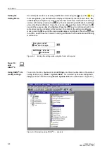
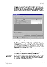
Page 146: ...IRIG B SyncBox IEC 60870 5 103 External minute impulses via binary input Time Synchroniza tion Settings for time synchronization may be found in DIGSI 4 under 6HWWLQJV 7LPH V QFKURQL DWLRQ Figure 5 46 Figure 5 46 Setting Window in DIGSI 4 example To open the 7LPH 6 QFKURQL DWLRQ RUPDW window the user should double click on 7LPH 6 QFKURQL DWLRQ See Figure 5 47 Note The device is delivered from the ...

Page 147: ...f an external source is selected only the selected synchronization source is used If the source fails the internal clock continues unsynchronized If time synchronization is to take place via a master control system the option IEC 60870 5 103 or PROFIBUS FMS must be selected Figure 5 47 not available in firmware Version 4 0 and 4 1 Table 5 10 Operating modes for time synchronization Item Operating ...

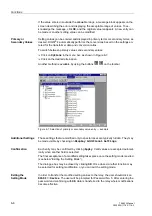
Page 148: ...on conditions you may delay the trigger of the error status condition even longer Changing the Syn chronization Mode When changing synchronization mode the hardware will change over to the new source within one second This causes breakdown of cyclical synchronization and the internal clock will be disrupted as at start up until the new synchronization source takes over After modification to the sy...

Page 149: ... 77 6 5 Earth Fault Protection in Earthed Systems 6 97 6 6 Earth Fault Protection Teleprotection Schemes 6 113 6 7 Weak Infeed Tripping 6 126 6 8 External Direct and Remote Tripping 6 130 6 9 Overcurrent Protection 6 132 6 10 High Current Switch On To Fault Protection 6 149 6 11 Automatic reclosure function 6 151 6 12 Synchronism and Voltage Check Dead line Dead bus check 6 181 6 13 Overvoltage Pr...

Page 150: ...navigate to the 3 6 67 0 7 display as shown in Figure 6 2 In general an item number appears in the menu list to the right of each selection Nav igation can be accomplished using the item number in place of the and keys This feature is particularly helpful in large menus e g setting lists Based on the ex ample above from the 0 1 0 18 the 6 77 1 6 display can be reached by press ing on the keypad an...

Page 151: ...be confirmed by pressing the key A blinking asterisk is an indication that setting modification mode is still open Other modifications can be made to settings even in sub menus if present as long as set ting modification mode is still open The actual modification of settings occurs once setting modification mode is closed see below Exiting the Setting Mode Figure 6 3 Example of setting modificatio...

Page 152: ... rect entries may be retracted in this manner To remain in the setting modification mode press the key until the response VFDSH is highlighted Press the key to confirm and the user can remain in setting modification mode without down loading modifications Figure 6 4 Ending the setting mode using the front control panel From PC with DIGSI 4 Using DIGSI 4 to modify settings To select a function doub...

Page 153: ...title of the setting and the right column of the dialogue box identified as the 9DOXH column contains the current value of the setting in text or numerical format When the mouse cursor is positioned over a numerical field in the 9DOXH column the allowable range is shown To modify a setting click on the setting value which is displayed in the 9DOXH column Text Values When a text setting value is se...

Page 154: ...ailable by using the buttons on the toolbar Figure 6 7 Selection of primary or secondary value entry example Additional Settings Those settings that are modified only in special cases are typically hidden They may be made visible by checking on LVSOD GGLWLRQDO 6HWWLQJV Confirmation Each entry may be confirmed by clicking SSO Valid values are accepted automat ically when another field is selected T...

Page 155: ...rent transformer polarity Instrument Trans former Nominal Values In the address 8QRP 35 0 5 and 8QRP 6 21 5 the device is in formed of the primary and secondary rated voltage line voltage of the voltage trans formers In the address 7 35 0 5 and 7 6 21 5 the primary and secondary rated current phase current of the current transformers are entered Please observe that the rated current transformer se...

Page 156: ...ter in ad dress M 8V QF 8OLQH is not required If however a transformer with a vector group unequal to zero separates the two voltage sources this setting must be used to compensate the phase shift according to the vector group of the transformer This setting is only available in DIGSI 4 under GGLWLRQDO 6HWWLQJV The phase an gle setting is defined as follows place Usync at zero degrees as reference...

Page 157: ...device contains four current measurement inputs three of which are connected to the set of current transformers The fourth current measuring input I4 may be utilised in various ways Connection of the I4 input to the earth current in the starpoint of the set of current transformers on the protected feeder normal connection refer to Appendix A Fig ure 1 9 Address is then set to WUDQVIRUPHU Q SURW OL...

Page 158: ...ired the following settings are applied Address WUDQVIRUPHU 1RW FRQQHFWHG Address SK 7 is then irrelevant In this case the zero sequence current for the protection functions is computed by means of the sum of the phase currents Rated Frequency Address 5DWHG UHTXHQF corresponds to the frequency at which the power system operates The preset value is dependent on the model number of the relay pur cha...

Page 159: ...y be modified with DIGSI 4 under Additional Settings Under address the maximum close command duration 70D 26 0 is set This applies to all close commands issued by the device It also determines the length of the close command pulse when a circuit breaker test cycle is issued via the device It must be set long enough to ensure that the circuit breaker has securely closed There is no risk in setting ...

Page 160: ...Usync Uline 0 360 0 Angle adjustment Usync Uline 215 U line Usync 0 80 1 20 1 00 Matching ratio U line Usync 220 I4 transformer not connected Neutral Current of the pro tected line Neutral Current of the paral lel line Starpoint Curr of earthed power transf Neutral Current of the protected line I4 current transformer is 221 I4 Iph CT 0 010 5 000 1 000 Matching ratio I4 Iph for CT s 230 Rated Frequ...

Page 161: ...t values for setting ranges and default settings refer to IN 1 A For the nominal current 5 A these values are to be multiplied by 5 242 T CBtest dead 0 00 30 00 sec 0 10 sec Dead Time for CB test auto reclosure Addr Setting Title Setting Options Default Setting Comments ...

Page 162: ... than one application While all setting groups are stored in the relay only one setting group may be active at a given time If multiple setting groups are not required Group A is the default selection and the rest of this sub section is of no importance If multiple setting groups are desired address US KJH 237 21 must have been set to QDEOHG in the relay configuration Refer to Chapter 5 Each of th...

Page 163: ...tory Settings The factory settings may be restored for a modified setting group To restore factory settings to a setting group the name of the setting group whose settings are to be re stored is highlighted Next select the menu option GLW and then click on 5HVHW A confirmation box appears click on HV to confirm restoration of factory settings Switching between Setting Groups The procedure to switc...

Page 164: ...etting Options Default Setting Comments 302 CHANGE Group A Group B Group C Group D Binary Input Protocol Group A Change to Another Setting Group F No Alarm Comments 7 Set Group Bit0 Setting Group Select Bit 0 8 Set Group Bit1 Setting Group Select Bit 1 Group A Group A Group B Group B Group C Group C Group D Group D ...

Page 165: ... and XOO6FDOH XUU These parameters influence the display of the operational meas ured values in percent If these ratings correspond to those of the voltage and current transformers the settings are the same as those in address and Section 6 1 1 General Line Data The settings of the line data in this case refers to the common data which is independ ent on the actual distance protection grading The ...

Page 166: ...orrespondingly the following applies to the per unit length reactance of a line with NCT Ratio of the current transformers NVT Ratio of the voltage transformers Calculation example 110 kV overhead line 150 mm2 similar to above R 1 0 19 Ω km X 1 0 42 Ω km Current transformer 600 A 1 A Voltage transformer 110 kV 0 1 kV The secondary per unit length reactance is therefore In address the following is ...

Page 167: ... calculated with primary or secondary values Calculation example 110 kV overhead line 150 mm2 with the following data R1 s 0 19 Ω km X1 s 0 42 Ω km Positive sequence impedance R0 s 0 53 Ω km X0 s 1 19 Ω km Zero sequence impedance where s line length The following results are obtained for the earth impedance ratio The earth impedance residual compensation factor setting for the first zone Z1 may be...

Page 168: ...if the quotients are calculated with primary or secondary values For overhead lines it is generally possible to calculate with scalar quantities as the angle of the zero sequence and positive sequence system only differ by an insignifi cant amount With cables however significant angle differences may exist as illustrat ed by the following example Calculation example 110 kV single conductor oil fil...

Page 169: ...hile the addresses and QJOH apply to the remaining zones Z1B and Z2 up to Z5 as seen from the relay location Parallel Line Mutual Impedance If the device is applied to a double circuit line parallel lines and parallel line compen sation for the distance and or fault location function is used the mutual coupling of the two lines must be considered A prerequisite for this is that the earth residual ...

Page 170: ...ault locator measuring error when the parallel line compensation is used The setting in address 5 7 2 3DU RPS is therefore only relevant for earth faults outside the protected feeder It provides the current ratio IE IEP for the earth cur rent balance of the distance protection in Figure 6 12 for the device at location II above which compensation should take place In general a presetting of 85 is s...

Page 171: ... the circuit breaker The device contains a circuit breaker state recognition function which processes the status of the circuit breaker auxiliary contacts as well as recognising switching operations close and open by processing of measured values refer also to Section 6 17 In address the remaining current 3ROH2SHQ XUUHQW which will definitely not be exceeded when the circuit breaker pole is open i...

Page 172: ... closing of the circuit breaker While the seal in time after all closures 6 7LPH DOO O address refer above is activated following each recognition of line energization the seal in time af ter manual closures 6 7LPH 0DQ O address is the time following manual closure during which special influence of the protection functions is activated e g in creased reach of the distance protection This setting c...

Page 173: ...o three pole coupling of the trip outputs If on the other hand this address is set to ZLWK 75 3 three pole coupling of the trip output three pole tripping only occurs when more than one pole is tripped Therefore if a single phase fault is located within the zone of tripping and a further arbitrary fault is outside the tripping zone single phase tripping is possible Even a further fault dur ing the...

Page 174: ...LS SK OW determines that the short circuit protection functions perform only a single pole trip in case of isolated two phase faults clear of ground provided that single pole tripping is possible and permitted This allows a single pole rapid automatic reclosure cycle for this kind of fault The trip type can be set to SROH OHDGLQJ SKDVH or SROH ODJJLQJ SKDVH The parameter is only available in ver s...

Page 175: ...9 XE XL Z1B Z5 33 7 00 1 00 Zero seq comp factor XE XL for Z1B Z5 1120 K0 Z1 0 000 4 000 1 000 Zero seq comp factor K0 for zone Z1 1121 Angle K0 Z1 135 00 135 00 0 00 Zero seq comp angle for zone Z1 1122 K0 Z1 0 000 4 000 1 000 Zero seq comp factor K0 higher zones Z1 1123 AngleI K0 Z1 135 00 135 00 0 00 Zero seq comp angle higher zones Z1 1126 RM RL ParalLine 0 00 8 00 0 00 Mutual Parallel Line co...

Page 176: ... 3 pole coupling 1156 Trip2phFlt 3pole 1pole leading phase 1pole lagging phase 3pole Trip type with 2phase faults Addr Setting Title Setting Options Default Setting Comments F No Alarm Comments 351 CB Aux L1 Circuit breaker aux contact Pole L1 352 CB Aux L2 Circuit breaker aux contact Pole L2 353 CB Aux L3 Circuit breaker aux contact Pole L3 379 CB 3p Closed CB aux contact 3pole Closed 380 CB 3p O...

Page 177: ...P command Phase L3 511 Relay TRIP Relay GENERAL TRIP command 512 Relay TRIP 1pL1 Relay TRIP command Only Phase L1 513 Relay TRIP 1pL2 Relay TRIP command Only Phase L2 514 Relay TRIP 1pL3 Relay TRIP command Only Phase L3 515 Relay TRIP 3ph Relay TRIP command Phases L123 536 Definitive TRIP Relay Definitive TRIP 510 Relay CLOSE Relay GENERAL CLOSE command 563 CB Alarm Supp CB alarm suppressed 533 IL...

Page 178: ...sed earth current measure ment a zero sequence current negative sequence current comparison as well as a displacement voltage measurement Earth Current 3I0 For earth current measurement the fundamental sum of the numerically filtered phase currents 3 I0 is monitored to detect if it exceeds the set value parameter 7KUHVKROG address It is stabilized against over operation resulting from un symmetric...

Page 179: ...age Neutral Displace ment Voltage 3U0 For the neutral displacement voltage recognition the displacement voltage 8 is numerically filtered and the fundamental frequency is monitored to recognize whether it exceeds the set threshold 8 7KUHVKROG The reset threshold is approximately 95 of the pick up threshold The U0 criterion may be disabled by applying the set ting Logical Combination The current an...

Page 180: ...d earth short circuit current 3I0 is defined as the sum of the phase currents IL1 IL2 IL3 which equals the star point current of the set of current transformers With regard to the setting 8 7KUHVKROG address care must be taken that operational unsymmetries do not cause a pick up 3U0 is defined as the sum of the phase earth voltages UL1 E UL2 E UL3 E If the U0 criterion should be ignored the addres...

Page 181: ...occurs during the evaluation the new measured values are immediately used for the calculation The fault evaluation is therefore always done with the measured val ues of the current fault condition Phase Phase Loops To calculate the phase phase loop for instance during a two phase short circuit L1 L2 Figure 6 19 the loop equation is where U I are the complex measured values and Z R jX is the comple...

Page 182: ...oops For the calculation of the phase earth loop for example during a L3 E short circuit Figure 6 21 it must be noted that the impedance of the earth return path does not correspond to the impedance of the phase In the loop equation ZE is replaced by ZE ZL ZL and the result is From this the line impedance can be extracted ILx ILy ILx ILy Measur ing syst Lx Ly from state recogni tion Rx y Xx y ULx ...

Page 183: ...ses During a L1 E fault for example the short circuit current in phase L1 also appears in the measuring loops L1 L2 and L3 L1 The earth current is also measured in the loops L2 E and L3 E Combined with load currents which may flow the unfaulted loops produce the so called apparent impedances which have nothing to do with the actual fault distance These apparent impedances in the unfaulted loops ar...

Page 184: ...lted phases Double Faults in Effectively Earthed Systems In systems with an effectively earthed star point each connection of a phase with earth results in a short circuit condition which must be isolated immediately by the closest protection systems Fault detection occurs in the faulted loop associated with the faulted phase With double earth faults fault detection is generally in two phase earth...

Page 185: ...e The earth current of the parallel line must be connected to the device for this purpose The loop equation is then modified as shown below refer also to Figure 6 21 where IEP is the earth current of the parallel line and the ratio ZM ZL is a constant line parameter resulting from the geometry of the double circuit line and the nature of the Table 6 2 Evaluation of the measured loops during multip...

Page 186: ...t be carried out as this would cause se vere overreach The relay located in position II in Figure 6 23 may therefore not be compensated Earth current balance is therefore additionally provided in the device which carries out a cross comparison of the earth currents in the two lines The compensation is only applied to the line end where the earth current of the parallel line is not substantially la...

Page 187: ...rth Faults in Effectively Earthed Systems The loop selection for double earth faults is set in address 3K IDXOWV Phase Phase Earth fault detection This setting can only be modified with DIGSI 4 under Additional Settings In general the ORFN OHDGLQJ blocking of the leading phase presetting is favourable because the leading phase earth loop tends to overreach especially in conjunction with large eart...

Page 188: ... 6 25 Sub section 6 2 3 1 and Figure 6 31 Sub section 6 2 4 1 The R value 5 ORDG address and 5 ORDG address must be set somewhat approx 10 smaller than the minimum load impedance which may occur The minimum load impedance results when the maximum load cur rent and minimum operating voltage exist Calculation example 110 kV overhead line 150 mm2 with the following data maximum transferrable load Pma...

Page 189: ...hreshold for dist meas 1215 Paral Line Comp NO YES NO Mutual coupling parall line com pensation 1232 SOTF zone with Pickup non directional with Zone Z1B Inactive Inactive Instantaneous trip after Swit chOnToFault 1241 R load Ø E 0 10 250 00 Ohm infin Ohm R load minimum Load Impe dance ph e 1242 ϕ load Ø E 20 60 45 PHI load maximum Load Angle ph e 1243 R load Ø Ø 0 10 250 00 Ohm infin Ohm R load mi...

Page 190: ...Dis Pickup 1pL1 Distance Pickup Phase L1 only 3682 Dis Pickup L1E Distance Pickup L1E 3683 Dis Pickup 1pL2 Distance Pickup Phase L2 only 3684 Dis Pickup L2E Distance Pickup L2E 3685 Dis Pickup L12 Distance Pickup L12 3686 Dis Pickup L12E Distance Pickup L12E 3687 Dis Pickup 1pL3 Distance Pickup Phase L3 only 3688 Dis Pickup L3E Distance Pickup L3E 3689 Dis Pickup L31 Distance Pickup L31 3690 Dis P...

Page 191: ...istance Pickup REVERSE 3741 Dis Z1 L1E Distance Pickup Z1 Loop L1E 3742 Dis Z1 L2E Distance Pickup Z1 Loop L2E 3743 Dis Z1 L3E Distance Pickup Z1 Loop L3E 3744 Dis Z1 L12 Distance Pickup Z1 Loop L12 3745 Dis Z1 L23 Distance Pickup Z1 Loop L23 3746 Dis Z1 L31 Distance Pickup Z1 Loop L31 3747 Dis Z1B L1E Distance Pickup Z1B Loop L1E 3748 Dis Z1B L2E Distance Pickup Z1B Loop L2E 3749 Dis Z1B L3E Dist...

Page 192: ...se in Z1 with single ph Flt 3824 DisTRIP3p Z1mf DisTRIP 3phase in Z1 with multi ph Flt 3813 Dis TripZ1B1p Distance TRIP single phase Z1B 3825 DisTRIP3p Z1Bsf DisTRIP 3phase in Z1B with single ph Flt 3826 DisTRIP3p Z1Bmf DisTRIP 3phase in Z1B with multi ph Flt 3816 Dis TripZ2 1p Distance TRIP single phase Z2 3817 Dis TripZ2 3p Distance TRIP 3phase in Z2 3818 Dis TripZ3 T3 Distance TRIP 3phase in Z3...

Page 193: ...t zone as an example In general the polygon is defined by means of a parallelogram which intersects the axes with the values R and X as well as the tilt ϕLine A load trapezoid with the setting RLoad und ϕLoad may be used to cut the area of the load impedance out of the polygon The axial coordinates can be set individually for each zone ϕLine RLoad und ϕLoad are common for all zones The parallelogr...

Page 194: ... circuit voltage during a close in fault is even too small for direction determination an unfaulted voltage is used This voltage is in theory quadrilateral to the actual short circuit voltage for both phase earth loops as well as for phase phase loops refer to Figure 6 26 This is taken into account when computing the direction vector by means of a 90 rotation In Table 6 3 the allocation of the mea...

Page 195: ...impedance as well as the load transferred across the line prior to fault in ception Accordingly the directional characteristic includes a safety margin with re spect to the borders of the first quadrant in the R X diagram Figure 6 27 As each zone may be set RUZDUG 5HYHUVH or 1RQ LUHFWLRQDO there is a sep arate mirrored directional characteristic for the forward and reverse direction Table 6 3 Allo...

Page 196: ...these voltages are equal to the corresponding generator e m f E and they do not change after fault inception the directional characteristic is shifted in the impedance diagram by the source impedance ZS1 E1 I1 In the case of a fault located at F1 Figure 6 28a the short circuit is located in the forward direction and the source impedance in the reverse direction For all fault locations right up to ...

Page 197: ...hin the operating polygon of a distance zone the affected loop is designated as picked up The loop informa tion is also converted to phase segregated alarms Further conditions for pick up of a zone are that the direction corresponds to the set direction for the zone and that the zone is not blocked by the power swing blocking refer to Sub section 6 3 1 Further more the distance protection must not...

Page 198: ...chart for the entire galvan ically interconnected system This diagram should reflect the line lengths with their pri mary reactance X in Ω phase For the reach of the distance zones the reactance X is the deciding quantities The first zone Z1 is usually set to cover 85 of the protected line without any trip time delay i e T1 0 00 s The protection clears faults in this range without additional time ...

Page 199: ...ises for example the resistance in arcs the earth distribution resist ance of earth points and others The setting must allow for these fault resistance but should at the same time not be larger than necessary On long heavily loaded lines the setting may extend into the load impedance range Fault detection due to overload conditions is then prevented with the load trapezoid Refer to the margin head...

Page 200: ...measured fault resistance decreases with current infeed from the opposite end Therefore for the arc resistance effective at the relay location calculated by means of calculation with constant arc voltage the current from the opposite end does not have to be taken into account Independent Zones Z1 up to Z5 By means of the setting parameter 02 each zone can be set RUZDUG or 5HYHUVH or 1RQ LUHFWLRQDO...

Page 201: ...e pole single pole tripping is then possible in the zones Z1 and Z2 While single pole tripping then usually applies to single phase faults in Z1 if the other conditions for single pole tripping are satisfied this may also be selected for the second zone with address 7ULS SROH Single pole tripping in zone 2 is only possible if this address is set to 6 The pre setting is 12 Controlled Zone Z1B The o...

Page 202: ... may be suppressed by changing the setting to VW 5 equals 1R In this case the overreaching zone Z1B is not released before and during the 1st automatic reclose cycle Zone Z1 is always released The setting only has an effect when the service condition of the automatic reclose function is input to the device via binary input Enable ARzones FNo 383 power system data 2 6 2 3 3 Settings Addr Setting Ti...

Page 203: ...aults in Z2 1321 Op mode Z3 Forward Reverse Non Directional Inactive Reverse Operating mode Z3 1322 R Z3 Ø Ø 0 05 250 00 Ohm 5 00 Ohm R Z3 Resistance for ph ph faults 1323 X Z3 0 05 250 00 Ohm 10 00 Ohm X Z3 Reactance 1324 RE Z3 Ø E 0 05 250 00 Ohm 10 00 Ohm RE Z3 Resistance for ph e faults 1325 T3 DELAY 0 00 30 00 sec 0 60 sec T3 delay 1331 Op mode Z4 Forward Reverse Non Directional Inactive Non ...

Page 204: ...rent values are to be multiplied by 5 The values of impedance are divided by 5 1343 X Z5 0 05 250 00 Ohm 12 00 Ohm X Z5 Reactance for Forward direction 1344 RE Z5 Ø E 0 05 250 00 Ohm 12 00 Ohm RE Z5 Resistance for ph e faults 1345 T5 DELAY 0 00 30 00 sec 0 90 sec T5 delay 1346 X Z5 0 05 250 00 Ohm 4 00 Ohm X Z5 Reactance for Reverse direction Addr Setting Title Setting Options Default Setting Comm...

Page 205: ...rolled zone for each fault impedance loop The basic shape of a MHO circle for one zone is shown in Figure 6 30 as an example Figure 6 30 Basic shape of a MHO circle characteristic The MHO circle is defined by the line of its diameter which intersects the origin of the coordinate system and the magnitude of the diameter which corresponds to the im pedance Zr which determines the reach The incline o...

Page 206: ...he calculation by means of a 90 rotation The unfaulted loop voltages also cause a displacement of the lower zenith Figure 6 31 Polarized MHO circle Characteristics of the MHO Circle As the quadrature or memorized voltage without load transfer equals the corre sponding generator voltage E and does not change after fault inception refer also to Figure 6 32 the lower zenith is shifted in the impedanc...

Page 207: ... two zeniths of the circle diameter and the fault impedance The zenith Zr corresponds to the set value for the zone under consideration Zr and ϕLine as shown in Figure 6 30 the zenith k ZS corresponds to the polarizing magnitude Therefore the difference phasors are Z1 ZF Zr Z2 ZF k ZS In the limiting case ZF is located on the perimeter of the circle In this case the angle between the two differenc...

Page 208: ...p The loop information is also converted to phase segregated information Further conditions for the pick up of a zone is that the zone may not be blocked by the power swing blocking refer also to Sub section 6 3 1 Furthermore the distance pro tection may not be blocked or switched off completely Figure 6 34 shows these con ditions Figure 6 34 Release logic of a zone Z1 used as an example Load area...

Page 209: ...ntire galvan ically interconnected system This diagram should reflect the line lengths with their pri mary impedance Z in Ω phase For the reach of the distance zones the impedances Z are the deciding quantities The first zone Z1 is usually set to cover 85 of the protected line without any trip time delay i e T1 0 00 s The protection clears faults in this range without additional time delay i e the...

Page 210: ...the first zone a setting of 85 of the line length should be applied which results in primary Z1prim 0 85 ZL 0 85 15 88 Ω 13 5 Ω or secondary Independent Zones Z1 up to Z5 By means of the setting parameter 02 each zone can be set RUZDUG or 5HYHUVH Address 2S PRGH 2S PRGH 2S PRGH 2S PRGH and 2S PRGH This allows any combination of forward or reverse graded zones Zones that are not required are set QD...

Page 211: ...s 5 The delay times for single phase and mul tiple phase faults can again be set separately 7 SKDVH address and 7 PXOWL SKDVH address Zone Z1B is usually used in combination with automatic reclosure and or teleprotec tion systems It can be activated internally by the teleprotection functions see also section 6 4 or the integrated automatic reclosure if available see also section 6 1 or externally ...

Page 212: ...e suppressed by changing the setting to VW 5 equals 1R In this case the overreaching zone Z1B is not released before and during the 1st automatic reclose cycle Zone Z1 is always released The setting only has an effect when the service condition of the automatic reclose function is input to the device via binary input Enable ARzones FNo 383 power system data 2 ...

Page 213: ...st AR Z1B NO YES YES Z1B enabled before 1st AR int or ext 1411 Op mode Z2 Forward Reverse Inactive Forward Operating mode Z2 1412 ZR Z2 0 05 200 00 Ohm 5 00 Ohm ZR Z2 Impedance Reach 1315 T2 1phase 0 00 30 00 sec 0 30 sec T2 1phase delay for single phase faults 1316 T2 multi phase 0 00 30 00 sec 0 30 sec T2multi ph delay for multi phase faults 1317 Trip 1pole Z2 NO YES NO Single pole trip for faul...

Page 214: ...6 C119 2 The indicated secondary current values and values of impedance for setting ranges and default settings refer to IN 1 A For the nominal current 5 A the current values are to be multiplied by 5 The values of impedance are divided by 5 ...

Page 215: ...one logic is shown in Figure 6 35 using for zone 1 Figure 6 36 for zone 2 and Figure 6 37 for the third zone Zones Z4 and Z5 function according to Figure 6 38 In the case of zones Z1 Z2 and Z1B single pole tripping is possible for single phase faults if the device version includes the single pole tripping option Therefore the event output in these cases is provided for each pole Different trip del...

Page 216: ...Z1 1p 3771 Dis T1 exp 3801 Dis G trip 3824 Dis trip Z1 3pm 3802 Dis trip 1polL1 1p Trip perm 0381 Dis FDZ2 L3 Dis FD Z2 L2 Dis FD Z2 L1 1 1 T2 1phase T 0 T 0 T2 multi phase 1 L1 L2 L3 L1 L2 L3 L3 L2 L1 L3 L2 L1 Tripping logic of the distance protection 1 L1 L2 L3 1 L1 L2 L3 Z2 undelayed see figure 6 24 3817 Dis trip Z2 3p 3803 Dis trip 1polL2 3804 Dis trip 1polL3 3805 Dis trip L123 3816 Dis trip Z...

Page 217: ...ossible to use the zone Z1B as a rapid autoclosure stage that only operates for single pole faults if for example only single pole automatic reclose cycles are executed It is possible for the 7SA522 to trip single pole during two phase faults without earth connection in the overreaching zone when single pole automatic reclosure is used As the device has an integrated teleprotection function refer ...

Page 218: ...ures 6 35 up to 6 39 The actual generation of the commands for the trip relay takes place in the tripping logic of the device refer to Sub section 6 17 4 No Yes VW 5 1 1 1 further not available 7HOHSURW LVW Dis Sig active Dis relZ1B T1B L3 Dis relZ1B T1B L2 Dis relZ1B T1B L1 L1 L2 L3 1pole tripping for 2pole faults L2 L1 L3 L1 L1 L2 L3 L2 L3 L3 L2 L1 L1 L2 L3 1 Dis FD Z1B L3 Dis FD Z1B L2 Dis FD Z...

Page 219: ...tance protection were already considered with the zone settings Sub sections 6 2 3 2 and 6 2 4 2 The parameter in address 627 RQH which determines the response during switching onto a short circuit was already set as part of the general data of the dis tance protection Sub section 6 2 2 2 Further setting options which affect the tripping are described as part of the tripping logic of the device re...

Page 220: ...h allows both the block ing of trips by the distance protection during power swings power swing blocking and the calculated tripping during unstable power swings out of step tripping 6 3 1 Method of Operation Detection of Power Swings System power swings are three phase symmetrical processes Therefore in general a certain degree of measured value symmetry may be assumed System power swings may how...

Page 221: ...rom the relay location have lost synchronism 4 The power transfer is unstable Figure 6 41 Pick up characteristic of the power swing detection for a polygon The same applies to the MHO circle characteristic refer to Figure 6 42 The power swing circle also has a distance Zdiff of 5 Ω at IN 1 A viz 1 Ω at IN 5 A from the largest zone circle If one or more reverse zones are set this impedance distance...

Page 222: ...FN The first zone Z1 and the overreaching zone Z1B are blocked during a power swing Faults in other zones are tripped with the associated grading time Blocking of only the higher zones WR EORFN The higher zones Z2 to Z5 are blocked during a power swing Only the first and the overreaching zone Z1 and Z1B remain active Blocking of the first two zones EORFN The first and second zone Z1 and Z2 and the...

Page 223: ... depends on the distance pro tection settings the power swing tripping can also only be active when the distance protection has been activated 6 3 2 Applying the Function Parameter Settings The power swing supplement is only active if it has been set to 3RZHU 6ZLQJ Q DEOHG address during the configuration The four possible programs may be set in address 3 6 2S PRGH as described in Sub section 6 3 ...

Page 224: ...unctions 6 76 7SA522 Manual C53000 G1176 C119 2 4167 Pow Swing L1 Power Swing detected in L1 4168 Pow Swing L2 Power Swing detected in L2 4169 Pow Swing L3 Power Swing detected in L3 F No Alarm Comments ...

Page 225: ...yed with T1 The 7SA522 permits Permissive Underreach Transfer Trip with Zone Acceleration Z1B PUTT Direct underreach Transfer Trip Permissive Overreach Transfer Trip POTT Unblocking with Overreach zon Z1B Blocking Signal Transmis sion Channels For the signal transmission at least one communication channel in each direction is required For example fibre optic connections or voice frequency modulate...

Page 226: ...ransfer trip scheme In the case of a fault inside zone Z1 the transfer trip signal is sent to the op posite line end The signal received there causes tripping if the fault is detected inside the zone Z1B in the set direction The transmitted signal may be prolonged by TS set table in address 6HQG 3URORQJ to compensate for possible differences in the pick up times at the two line ends The distance p...

Page 227: ...2 4 2 under margin head ing Independent Zones Z1 up to Z5 and Controlled Zone Z1B On two terminal lines the signal transmission may be done phase segregated On three terminal lines the transmit signal is sent to both opposite line ends The receive signals are then combined with an OR logic function By means of the parameter LQH RQILJ address the device is informed whether it has one or two opposit...

Page 228: ... of the shorter line section but at least beyond the tee off point The overreaching zone Z1B is not re quired here It may however be activated by internal automatic reclosure or external criteria via the binary input QDEOH 5 RQHV refer also to Figure 6 39 bottom The advantage compared to the permissive underreach transfer trip with zone accel eration lies in the fact that both line ends are trippe...

Page 229: ...ive This mode can also be used on extremely short lines where a setting of 85 of line length for zone Z1 is not possible and accordingly selective non delayed tripping could not be achieved In this case however zone Z1 must be delayed by T1 to avoid non selective tripping by zone Z1 Figure 6 47 shows the operation scheme If the distance protection recognizes a fault inside the overreaching zone Z1...

Page 230: ...r also to Sub section 6 2 4 2 under margin head ing Controlled Zone Z1B On two terminal lines the signal transmission may be phase segregated Send and receive circuits in this case are built up for each phase On three terminal lines the send signal is transmitted to both opposite ends The receive signals are then com bined with the logical AND function as all three line ends must transmit during a...

Page 231: ... Section 6 7 Figure 6 48 Logic diagram of the permissive overreach transfer trip POTT scheme one line end Two terminals Dis Telep off 1 Dis Z1B L1 Dis Z1B L2 Dis Z1B L3 Dis Z1B Dis forward 6HQG 3URORQJ T 0 Dis T RecCh1L1 Dis T RecCh1 Dis T RecCh1L2 1 1 1 Dis Enable Z1B T1B L1 DisTel Rec Ch1 DisTel Rec Ch2 Three terminals Two terminals Three terminals 1 LQH RQILJ 1 Trip command T 0 T 0 T 0 1 1 1 1 ...

Page 232: ...f0 is transmitted If the unblock frequency fU is faultlessly received from the opposite end a release sig nal is routed to the trip logic Accordingly it is a prerequisite for fast tripping that the fault is recognized inside Z1B in the forward direction at both line ends The distance protection is set such that the overreaching zone Z1B reaches beyond the opposite station approximately 120 of line...

Page 233: ...ived at the other line end because the short circuit on the line causes too severe an attenuation or reflection of the signal neither the un block signal e g LV 7 8 XE nor the block signal LV 7 8 EO is re ceived at the receiving end In this case the release Unblock 1 is issued after a security delay time of 20 ms and passed onto the receive logic This release is how ever removed after a further 10...

Page 234: ... 1 1 1 1 1 Dis PICKUP Unblock 1 Unblock 2 Unblock L1 Unblock L2 Unblock L3 T 0 2108 7 9 from unblock logic Figure 6 51 from unblock logic Figure 6 51 1 Transient blocking section 6 4 1 6 Two terminals Three terminals Dis Telep off 4003 Dis Telep Blk Dis Telep OFF 4052 Dis T SEND L1 4057 Dis T SEND L2 4058 Dis T SEND L3 4059 Dis T SEND 4056 Echo function section 6 4 1 7 Weak infeed trip section 6 7...

Page 235: ...ump detection i e LV XPS ORFN LQJ routed in parallel with only a short delay to allow for signal trans mission is required before Z1b trips A trip can be achieved with this scheme even if no signal reaches the opposite end It is therefore mainly used on long lines when the signal must be transmitted via the protected line with power line carrier PLC and the Dis T UB ub1L1 0 20 ms 100 100 ms 1 Unbl...

Page 236: ... the blocking scheme for one line end The relevant distance zone for this scheme is the overreach zone Z1B Its reach di rection must therefore be set to RUZDUG In the case of distance protection with po lygonal characteristic in address 2S PRGH refer also to Sub section 6 2 3 2 under margin heading Controlled Zone Z1B in the case of distance protec tion with MHO characteristic in address 2S PRGH r...

Page 237: ...ls Three terminals 1 1 1 1 7U ON DLW 7LPH T T 7U ON ORFN7LPH Transiente Block Transient Block Dis T Trans Blk Two terminals Three terminals Two terminals Three terminals Two terminals Three terminals Dis Telep off 4003 Dis Telep Blk 4006 DisTel Rec Ch2 4010 Dis T RecCh1L1 4007 Dis T RecCh1L2 4008 Dis T RecCh1L3 4009 Dis Telep OFF 4052 Dis T SEND 4056 Dis T BL STOP 4070 Dis T SEND L1 4057 Dis T BL ...

Page 238: ...overreach schemes the transient blocking provides additional security against erroneous signals due to transients caused by clearance of an external fault or by fault direction reversal during clearance of a fault on a parallel line The principle of transient blocking scheme is that following the incidence of an external fault the formation of a release signal is prevented for a certain settable t...

Page 239: ...al AND gate The distance protection must neither be switched off nor blocked as it would otherwise always produce an echo due to the missing fault detection If however the time delayed overcurrent protection is used as an emergency function an echo is nevertheless possible if the distance protection is out of service because the fault detection of the emergency overcurrent protection replaces the ...

Page 240: ...eleprotection supplement is only in service if it is set during the configuration to one of the possible modes of operation in address Depend ing on this configuration setting only those parameters that are relevant to the select ed mode of operation will appear here If the teleprotection supplement is not required address is 7HOHSURW LVW LVDEOHG Note The 2 6 1 F No 4246 must be separately assigne...

Page 241: ... set incorrectly The distance protection at A would not pick up and there fore interpret this as a fault with single end infeed from B echo from A or no block sig nal at A This would result in a false trip Figure 6 56 Distance protection setting with permissive overreach schemes Time Settings The send signal prolongation 6HQG 3URORQJ address must ensure that the send signal reliably reaches the op...

Page 242: ...e preset value is generally sufficient Echo Function In the case of line ends with weak infeed the echo function is sensible in conjunction with permissive overreach transfer schemes POTT and UNBLOCKING with release signal so that the feeding line end is also released The echo function can be enabled under address 7 HDN QIHHG 2 RQO or disabled 2 With this switch the weak infeed tripping function c...

Page 243: ...protection ON 4002 Dis Telep OFF Distance Teleprotection OFF 4003 Dis Telep Blk Distance Teleprotection BLOCK 4006 DisTel Rec Ch1 Dis Tele Carrier RECEPTION Channel 1 4007 Dis T RecCh1L1 Dis Tele Carrier RECEPTION Channel 1 L1 4008 Dis T RecCh1L2 Dis Tele Carrier RECEPTION Channel 1 L2 4009 Dis T RecCh1L3 Dis Tele Carrier RECEPTION Channel 1 L3 4010 Dis T Rec Ch2 Dis Tele Carrier RECEPTION Channel...

Page 244: ...END signal L2 4059 Dis T SEND L3 Dis Telep Carrier SEND signal L3 4068 Dis T Trans Blk Dis Telep Transient Blocking 4070 Dis T BL STOP Dis Tele Blocking carrier STOP signal 4060 DisJumpBlocking Dis Tele Blocking Send signal with jump 4080 Dis T UB Fail1 Dis Tele Unblocking FAILURE Channel 1 4081 Dis T UB Fail2 Dis Tele Unblocking FAILURE Channel 2 4082 Dis T BL STOPL1 DisTel Blocking carrier STOP ...

Page 245: ... a short circuit any stage or several stages may be switched to undelayed tripping 6 5 1 Method of Operation Measured value The earth current is the negative sum of the three phase currents i o w IE 3 I0 IL1 IL2 IL3 Depending on the version ordered and the configured application for the fourth current input I4 of the device the earth current can be measured or cal culated If the input I4 is connec...

Page 246: ... possible HV or not possible 1R 627 7ULS determines whether during energization of the feeder onto a fault tripping with this stage shall be non delayed HV or not 1R and QUXVK ON which is used to switch the inrush stabilization rush blocking on HV or off 1R Figure 6 57 Logic diagram of the 3I0 stage Definite Time High Set Current Stage 3I0 The logic of the high set current stage 3I0 is the same as...

Page 247: ... stage inverse time overcurrent protection for example IEC curves Inverse Time Over current Stage with Inverse Logarith mic Characteristic The inverse logarithmic characteristic differs from the other inverse characteristics mainly by the fact that the shape of the curve can be influenced by a number of pa rameters The slope S 7LPH LDO and a time shift 7 3PD which directly af fect the curve can be...

Page 248: ...e phase current As the phase currents increase the pick up thresholds are increased Figure 6 60 The sta bilization factor slope may be changed by means of the parameter SK 67 6ORSH setting address 3104 section 6 5 2 It applies to all stages Figure 6 60 Phase current stabilization Yes No Reverse Forward Non Directional 1 1 inrush stabilization direction determination forwards reverse Yes No Yes No ...

Page 249: ...ntent is greater than the set val ue the affected stage is blocked Direction Determi nation with the Zero Sequence System The direction determination is carried out with the measured current IE 3 I0 which is compared to a polarization voltage UP which results from the measured volt age UE 3 U0 refer to Figure 6 61 The direction determination may also be carried out with the earth current IE and th...

Page 250: ...U0 These signals must also have a minimum magnitude of or 8 Blocking The earth fault protection can be blocked by the distance protection If in this case a fault is detected by the distance protection the earth fault protection will not operate This gives the selective fault clearance by the distance protection preference over trip ping by the earth fault protection The earth fault protection can ...

Page 251: ...ot required the setting 1R is applied The earth fault protection should be blocked during single pole automatic reclose dead time to avoid pick up with the false zero sequence values arising during this state address 2 S HDG7LP A setting of HV is therefore only required if single pole tripping is implemented Otherwise the setting 1R presetting remains Definite Time Stages First of all the mode for...

Page 252: ...d the configuration Section 5 1 ad dress that was selected If an inverse overcurrent stage is not required the ad dress is set to DUWK DXOW 2 HILQLWH 7LPH The 3I0P stage can then be used as a fourth definite time stage refer to Definite Time Stages above or deactivated In the case of the IEC curves address DUWK DXOW 2 72 the following alternatives are available in the address XUYH QYHUVH normal in...

Page 253: ...ength time delay can also be set if this is required The setting GG 7 address is added to the time of the set curve Inverse Time Over current Stage with Logarithmic Inverse Character istic For the inverse time overcurrent stage with logarithmic inverse characteristic the op erating mode is initially set 2S PRGH S address This stage can be set to operate forward usually towards line or reverse dire...

Page 254: ...he angle of which is compared to a polarizing quantity Sub section 6 5 1 The desired polarizing signal s is set in 32 5 7 21 address The presetting ZLWK 8R DQG generally also applies when only UE 3U0 is used as a polarizing signal If there is no transformer star point current IY connected to the device auto matically only UE influences the direction determination If the direction determination mus...

Page 255: ...ed when setting the earth current stage Initially it must be determined which stage must operate in conjunction with the tele protection This stage must be set directional in the forward direction If for example the 3I0 stage should operate as directional comparison the address 2S PRGH is set to RUZDUG refer to Definite Time Stages above page 6 101 Furthermore the device must be informed that the ...

Page 256: ...se currents increase refer also to Figure 6 60 By means of the setting in address SK 67 6ORSH the preset value of 10 for all stages can be jointly changed for all stages This setting can only be modified with DIGSI 4 under Addi tional Settings Inrush Stabilization The inrush stabilization is only required if the device is applied to transformer feeders or on lines that end on a transformer in this...

Page 257: ...Op mode 3I0 Forward Reverse Non Directional Inactive Inactive Operating mode 3111 3I0 0 50 25 00 A 4 00 A 3I0 Pickup 3112 T 3I0 0 00 30 00 sec 0 30 sec T 3I0 Time delay 3113 3I0 Telep BI NO YES NO Instantaneous trip via Tele prot BI 3114 3I0 SOTF Trip NO YES NO Instantaneous trip after Swit chOnToFault 3115 3I0 InrushBlk NO YES NO Inrush Blocking 3120 Op mode 3I0 Forward Reverse Non Directional In...

Page 258: ...0 00 30 00 sec 5 80 sec 3I0p Maximum Time Delay 3147 Add T DELAY 0 00 30 00 sec 1 20 sec Additional Time Delay 3148 3I0p Telep BI NO YES NO Instantaneous trip via Tele prot BI 3149 3I0p SOTF Trip NO YES NO Instantaneous trip after Swit chOnToFault 3150 3I0p InrushBlk NO YES NO Inrush Blocking 3151 IEC Curve Normal Inverse Very Inverse Extremely Inverse Long time inverse Normal Inverse IEC Curve 31...

Page 259: ...rth current IY for polari zing 3166 3U2 0 5 10 0 V 0 5 V Min neg seq polarizing voltage 3U2 3167 3I2 0 05 1 00 A 0 05 A Min neg seq polarizing cur rent 3I2 3170 2nd InrushRest 10 45 15 2nd harmonic ratio for inrush restraint 3171 Imax InrushRest 0 50 25 00 A 7 50 A Max Current overriding inrush restraint 3172 SOTF Op Mode with Pickup non directional with Pickup and direction with Pickup and direct...

Page 260: ...ed OFF 1332 E F BLOCK Earth fault protection is BLOCKED 1333 E F ACTIVE Earth fault protection is ACTIVE 1345 EF Pickup Earth fault protection PICKED UP 1354 EF 3I0 Pickup E F 3I0 PICKED UP 1355 EF 3I0 Pickup E F 3I0 PICKED UP 1356 EF 3I0 Pickup E F 3I0 PICKED UP 1357 EF 3I0p Pickup E F 3I0p PICKED UP 1358 EF forward E F picked up FORWARD 1359 EF reverse E F picked up REVERSE 1361 EF Trip E F Gene...

Page 261: ...heme Blocking scheme Blocking of the directional stage A further stage may be set as a non directional back up stage Signal Transmis sion Channels For the signal transmission one channel in each direction is required For example fibre optic connections or voice frequency modulated high frequency channels via pilot cables power line carrier or microwave radio links can be used for this purpose If t...

Page 262: ...n scheme is shown When the earth fault protection recognizes a fault in the forward direction it initially sends a permissive signal to the opposite line end If a permissive signal is also re ceived from the remote end the trip signal is passed on to the tripping relay Accord ingly it is a prerequisite for fast tripping that the fault is recognized in the forward direc tion at both line ends The s...

Page 263: ...e Transient Blocking refer to Sub section 6 6 1 4 On feeders with only a single sided infeed or where the star point is only earthed be hind one line end the line end without zero sequence current cannot generate a per missive signal as fault detection does not take place there To ensure tripping by the directional comparison even in this case the device contains a special function This Weak Infee...

Page 264: ...s faultlessly received from the opposite end a release sig nal is routed to the trip logic A pre condition for fast fault clearance is therefore that the earth fault is recognized in the forward direction at both line ends The send signal can be prolonged by TS parameter setting The prolongation of the send signal only comes into effect if the protection has already issued a trip command This ensu...

Page 265: ...on reversal resulting during the clearance of faults on par allel lines is neutralized by the Transient Blocking refer to Sub section 6 6 1 4 On lines where there is only a single sided infeed or where the starpoint is only earthed behind one line end the line end without zero sequence current cannot generate a permissive signal as fault detection does not take place there To also ensure tripping ...

Page 266: ...of the transmitted signal at the fault location may be so severe that reception at the other line cannot necessarily be guaranteed In Figure 6 69 the operation scheme is shown Earth faults in the forward direction cause tripping if a blocking signal is not received from the opposite line end Due to possible differences in the pick up time delays of the devices at both line ends and due to the sign...

Page 267: ...J address the device is informed as to whether it has one or two op posite line ends Figure 6 70 Logic diagram of the blocking scheme one line end 6 6 1 4 Transient Blocking Transient blocking provides additional security against erroneous signals due to tran sients caused by clearance of an external fault or by fault direction reversal during clearance of a fault on a parallel line The principle ...

Page 268: ...ak in feed does not transmit a permissive release signal To achieve rapid tripping at both line ends under these conditions the device has a special supplement for lines with weak zero sequence infeed To enable even the line end with the weak infeed to trip 7SA522 provides a weak in feed tripping supplement As this is a separate protection function with a dedicated trip command it is described in ...

Page 269: ... the circuit breaker at the non feeding line end is open this delay of the echo signal is not required The echo delay time may then be bypassed The circuit breaker switch ing state is provided by the central information control functions refer to Section 6 17 The echo impulse is then transmitted alarm output 2 6 1 the duration of which can be set with the parameter 7ULS 7 16 21 After transmission ...

Page 270: ...rder to ensure the blocking signal in the case of the blocking scheme If during an earth fault accord ing to Figure 6 73 the protection at B does not recognize the fault this would be inter preted as a fault with single sided infeed from A echo from B or no blocking signal from B which would lead to unwanted tripping by the protection at A For this reason the earth fault protection has an earth cu...

Page 271: ...ifferent protection function or other stage In the case of the blocking scheme 2 1 the transmit signal is always prolonged by this time In this case it corresponds to a transient blocking following a reverse fault This setting can only be modified with DIGSI 4 under Additional Settings The release of the directional tripping can be delayed by means of the permissive sig nal delay 7 9 address This ...

Page 272: ...ion 6 7 The comments above regarding the setting of the current stage R0LQ 7HOHSURW address must be noted as well as the margin heading Earth Fault Protection Prerequisites The echo delay time 7ULS FKR address must be set long enough to ensure that no unwanted echo signals are generated due to differences in the pick up times of the earth fault protection fault detection at the two line ends durin...

Page 273: ...arm Comments 1311 EF Teleprot ON E F Teleprotection ON 1312 EF TeleprotOFF E F Teleprotection OFF 1313 EF TeleprotBLK E F Teleprotection BLOCK 1318 EF Rec Ch1 E F Carrier RECEPTION Channel 1 1319 EF Rec Ch2 E F Carrier RECEPTION Channel 2 1320 EF UB ub 1 E F Unblocking UNBLOCK Channel 1 1321 EF UB bl 1 E F Unblocking BLOCK Channel 1 1322 EF UB ub 2 E F Unblocking UNBLOCK Channel 2 1323 EF UB bl 2 ...

Page 274: ...rip command In Figure 6 75 the logic diagram of the weak infeed tripping is shown It may be acti vated in address 7 HDN QIHHG Weak Infeed MODE 2 DQG 75 3 or deactivated 2 If this switch is set to 2 RQO the tripping is also disabled however the echo function to release the infeeding line end is activated refer also to Sub section 6 4 1 7 and 6 6 1 5 The tripping function can be blocked at any time ...

Page 275: ...t OFF BLOCK 50 40 ms S R Q PICKUP L1 CB closed L1 1 W I Pickup L1 BLOCK Weak Inf UL2 UL2 81 592 7 S R Q PICKUP L2 CB closed L2 1 UL3 UL3 81 592 7 S R Q PICKUP L3 CB closed L3 1 with earth fault protection with dist protection applies to PUTT and POTT with unblockschemes the unblock signals acc to Fig 6 51 apply applies to direc comp with unblock schemes the unblock signals apply 4203 Dis T RecCh1L...

Page 276: ...e end is activated There is however no tripping at the line end with missing or weak infeed condition As the weak infeed measures are dependent on the signal reception from the opposite line end they only make sense if the protection is coordi nated with teleprotection refer to Section 6 4 and or 6 6 The receive signal is a functional component of the trip condition Accordingly the weak infeed tri...

Page 277: ...Trip function 4221 WeakInf OFF Weak Infeed Trip fct is switched OFF 4222 Weak Inf BLOCK Weak Infeed Trip function is BLOCKED 4223 Weak Inf ACTIVE Weak Infeed Trip function is ACTIVE 4231 WeakInf PICKUP Weak Infeed Trip function PICKED UP 4232 W I Pickup L1 Weak Infeed Trip function PICKUP L1 4233 W I Pickup L2 Weak Infeed Trip function PICKUP L2 4234 W I Pickup L3 Weak Infeed Trip function PICKUP ...

Page 278: ...ipping at the opposite line end one separate communication channel is required for each required transmission direction For this purpose fibre optic commu nication channels could for example be used or communication cables with voice fre quency modulated HF channels power line carrier or microwave radio channels If the trip command of the distance protection is to be transmitted it is best to use ...

Page 279: ...s set for the device in general in address 240A Sub section 6 1 1 Reliable operation of the circuit breaker is therefore ensured even if the initiating signal pulse is very short 6 8 3 Settings 6 8 4 Information Overview Addr Setting Title Setting Options Default Setting Comments 2201 FCT Direct Trip ON OFF OFF Direct Transfer Trip DTT 2202 Trip Time DELAY 0 00 30 00 sec 0 01 sec Trip Time Delay F...

Page 280: ...iately blocked and the emergency operation is activated If the overcurrent protection is configured as back up overcurrent protection it func tions independently of the other protective and monitoring functions therefore also in dependent of the distance protection The back up overcurrent protection could for in stance be used as the only short circuit protection if the voltage transformers are no...

Page 281: ...s then also possible if very small as well as large earth fault currents may occur If the fourth current input I4 is used e g for a power transformer star point current or for the earth current of a parallel line the device derives the earth current from the phase currents Naturally in this case also all three phase currents derived from a set of three star connected current transformers must be a...

Page 282: ... selection of the available characteristics was already done during the configuration of the protection functions Furthermore an additional constant time delay 7 S GG address 2646 may be selected which are added to the current dependant time derived from the IDMT characteristic The available char acteristics are shown in the technical data Section 10 9 Figure 6 78 shows the logic diagram The setti...

Page 283: ...for IEC curves 1 Yes No S 627 Yes No further stages 3I0P 1 E IE 2652 7 S 7LPH LDO T 0 t I IP 1 L1 2642 7 S 7LPH LDO 7 S GG T 0 2660 XUYH t I IL3 IL2 IL1 L2 L3 3 2656 7 S GG S 3 83 switch onto fault T 0 627 7LPH S 7HOH Ip Pickup L3 Ip Pickup L2 Ip Trip L3 Ip Trip L2 Ip Pickup L1 Ip Trip L1 3I0p Trip 3I0p Pickup 7106 BLOCK O C Ip 7110 O C InstTRIP ...

Page 284: ...ped without delay The two sets of current transformers are connected in parallel such that the current sum IA IB represents the current flowing towards the line iso lator The stub protection is an overcurrent protection which is only in service when the state of the line isolator indicates the open condition via a binary input 678 1 The binary input must therefore be operated via an auxiliary cont...

Page 285: ...ection signals of the individual phases and earth and the individual stag es are combined in such a manner that both the phase information as well as the stage information of the picked up stages can be output Table 6 4 In the case of the trip signals the stage which resulted in the trip command is also in dicated If the device has the option to trip single pole and this option has been acti vated...

Page 286: ...XS 7163 I Pickup L3 I Pickup L3 Ip Pickup L3 I STUB Pickup L3 6 77 6 78 6 80 2 3LFNXS 7164 I Pickup E I Pickup E Ip Pickup E I STUB Pickup E 6 77 6 78 6 80 2 3LFNXS 7165 I Pickup L1 I Pickup L2 I Pickup L3 I Pickup E 6 77 6 77 6 77 6 77 2 3 83 7191 I Pickup L1 I Pickup L2 I Pickup L3 I Pickup E 2 3 83 7192 Ip Pickup L1 Ip Pickup L2 Ip Pickup L3 Ip Pickup E 6 78 6 78 6 78 6 78 2 3 83 S 7193 I STUB ...

Page 287: ...ay be sensible The time delay depends on the severity and duration of the transient overcurrents as well as on which stages were selected for the fast switch onto fault clearance High Set Overcurrent Stages Iph 3I0 The I stages SK address and address along with the I stages or the Ip stages result in a dual stage characteristic Of course it is also possible to combine all three stages If a particu...

Page 288: ...han 2365 A primary or 19 7 A secondary the fault is definitely on the protected feeder This fault may be cleared immediately by the overcurrent protection Comment The calculation was carried out with scalar quantities which is sufficient for overhead lines If there is a large difference in the angle of the source and line imped ance the calculation must be done with complex values An analogous cal...

Page 289: ... the settings these can be op tionally entered as primary or secondary values When applying the setting parame ters as secondary values the primary currents must be converted to the secondary side of the current transformer Calculation example 110 kV overhead line 150 mm2 as in the example in Sub section 6 2 3 2 or 6 2 4 2 maximum transmittable power Pmax 120 MVA corresponds to Imax 630 A current ...

Page 290: ... that the I stages trip without time delay following pick up if an operate signal is present at the binary input if the setting is 7HOHS 1R the set trip time delays always come into force If the I stage is to trip when switching the line on to a fault with or without a short de lay 627 7LPH address see above and refer to Sub section Gener al the parameter 627 address is set to Yes We recommend how...

Page 291: ...on shorter tripping times are advisable one grading time step above the fast tripping stage as this function is only activated in the case of the loss of the local measured voltage The time multiplier setting 7 S 7LPH LDO address can usually be set smaller according to a separate earth fault grading plan In addition to the current dependant time delay an additional constant time length de lay can ...

Page 292: ... fast tripping stage as this function is only activated in the case of the loss of the local measured voltage The time multiplier setting 7LPH LDO 7 S address can usually be set smaller according to a separate earth fault grading plan In addition to the current dependant time delay an additional constant time length de lay can be set if required The setting 7 S GG address for phase currents and 7 ...

Page 293: ... the minimum single phase current The time settings 7 SK 678 address and 7 678 address are set to for this application to prevent the protection from operating while the line iso lator is closed They may however also be used to implement an independent back up stage If this stage is applied differently similar considerations as for the other overcurrent stages apply The parameter 678 7HOHS address...

Page 294: ...00 sec 0 50 sec T 3I0 Time delay 2624 I Telep BI NO YES NO Instantaneous trip via Teleprot BI 2625 I SOTF NO YES NO Instantaneous trip after Swit chOnToFault 2640 Ip 0 10 4 00 A infin A Ip Pickup 2641 Ip MinT DELAY 0 00 30 00 sec 1 20 sec Ip Minimum Time Delay 2642 T Ip Time Dial 0 05 3 00 sec 0 50 sec T Ip Time Dial 2643 Time Dial TD Ip 0 50 15 00 5 00 Time Dial TD Ip 2644 T Ip Time Dial 0 05 15 ...

Page 295: ...t chOnToFault 2630 Iph STUB 0 10 25 00 A 0 50 A Iph STUB Pickup 2631 T Iph STUB 0 00 30 00 sec 0 00 sec T Iph STUB Time delay 2632 3I0 STUB 0 05 25 00 A 0 20 A 3I0 STUB Pickup 2633 T 3I0 STUB 0 00 30 00 sec 0 00 sec T 3I0 STUB Time delay 2634 I STUB Telep BI NO YES NO Instantaneous trip via Teleprot BI 2635 I STUB SOTF NO YES NO Instantaneous trip after Swit chOnToFault Addr Setting Title Setting ...

Page 296: ...up O C Pickup L31 7181 O C Pickup L31E Backup O C Pickup L31E 7182 O C Pickup L23 Backup O C Pickup L23 7183 O C Pickup L23E Backup O C Pickup L23E 7184 O C Pickup L123 Backup O C Pickup L123 7185 O C PickupL123E Backup O C Pickup L123E 7191 O C PICKUP I Backup O C Pickup I 7192 O C PICKUP I Backup O C Pickup I 7193 O C PICKUP Ip Backup O C Pickup Ip 7201 I STUB PICKUP O C I STUB Pickup 7211 O C T...

Page 297: ...econdary circuit following the switching off of large currents practically have no influence on the high current pick up operation Figure 6 81 shows the logic diagram The high current switch on to fault function can be phase segregated or three phase Following manual closure of the circuit breaker it always functions three phase via the release signal 627 2 5HOHDVH which is derived from the centra...

Page 298: ...closure dead time on a parallel feeder It is recommended to set at least 2 5 times the rated current of the feeder 6 10 3 Settings The indicated secondary current values for setting ranges and default settings refer to IN 1 A For the nominal current 5 A these values are to be multiplied by 5 6 10 4 Information Overview Addr Setting Title Setting Options Default Setting Comments 2401 FCT SOTF O C O...

Page 299: ... e g overhead line in block with a transformer or overhead line cable it must be ensured that reclosure can only be performed in the event of a fault on the overhead line In the version with single pole tripping the 7SA522 allows phase selective single pole tripping A single and three pole single and multiple shot automatic reclosure function is integrated depending on the ordered version The 7SA5...

Page 300: ...n 6 4 the signal transmission logic controls the overraching zone i e it determines whether an undelayed trip or delayed with T1B is permitted in the event of faults in the overreaching zone i e up to the reach limit of zone Z1B at both line ends simultaneously Whether the automatic reclosure device is ready for reclosure or not is irrelevant because the teleprotection function ensures the selecti...

Page 301: ...e a reclosure will be of no use here Examples for this in the 7SA522 are the overload pro tection and overvoltage protection Action times It is often desirable to remove the ready for reclosure state if the short circuit condition was sustained for a certain time e g because it is assumed that the arc has burned in to such an extent that there is no longer any chance of automatic arc extinction du...

Page 302: ...tarting Since the action time for the 1st cycle has already expired at this time this cycle cannot start the automatic reclosure circuit However the 2nd cycle which is also able to start the recloser is activated im mediately This 2nd cycle therefor starts the automatic reclosure circuit the 1st cycle is practically skipped Operating modes of the automatic reclosure function The dead times in othe...

Page 303: ... blocked for a Manual Close blocking time 7 2 0 If a trip command is issued during this time it can be assumed that a metallic short circuit is the cause e g closed earth switch Every trip command within this time is therefore a final trip With the user definable logic functions CFC further control functions may also be treated like a Manual Close command Interrogation of circuit breaker ready sta...

Page 304: ...e control by trip command see above under title Operating modes of the automatic reclosure function page 6 152 with the mode control by starting the type of fault indicated by the protection function s issueing the start is still valid If three pole reclose cycles are not allowed reclosure is blocked dynamically The trip command is final The latter also applies if the CB trips two poles following ...

Page 305: ...cycles starts with reset of the trip command or opening of the circuit breaker pole auxiliary contact criterion The cir cuit breaker receives a close command after the dead time At the same time the ad justable reclaim time is started If the reclosure is blocked during the dead time following a single pole trip optional immediate three pole tripping can take place forced three pole coupling If the...

Page 306: ... cycles are independent of each other Each one has separate action and dead times can operate single or three pole and can be blocked separately via binary inputs The parameters and intervention possibilities of the fourth cycle also apply to the fifth cycle and onwards The sequence is the same in principle as in the different reclosure programs described above However if the first reclosure attem...

Page 307: ...ot disappear following a trip reclosure can be prevented A prerequisite for this function is that the voltage transformers are connected on the line side of the circuit breaker To select this function the dead line check must be activated The automatic reclosure function then checks the discon nected line for no voltage The line must have been without voltage for at least an ad equate measuring ti...

Page 308: ...st fed from busbar A i e the side with the defined dead times With the adaptive dead time the automatic reclosure function at line end II decides in dependently if and when reclosure is sensible and is therefor allowed and when it is not The criterion is the voltage on the line at end II which is fed from end I following reclosure there Reclosure therefore takes place at end II as soon as it is ap...

Page 309: ...ure was successful This means that following reclosure one further possible local fault detection is waited for This delay prevents unneces sary closing at the remote end on the one hand but also increases the time until reclo sure takes place there This is not critical for a single pole interruption or in radial or meshed networks because no stability problems are expected under these conditions ...

Page 310: ...quired by external recloser device 5HOD 75 3 SK trip protective device 3 pole 5HOD 75 3 S trip protective device 1 pole phase L1 5HOD 75 3 SK trip protective device 3 pole 5HOD 75 3 S trip protective device 1 pole phase L2 5HOD 75 3 SK trip protective device 3 pole 5HOD 75 3 S trip protective device 1 pole phase L3 In order to obtain a phase segragated trip indication the respective single pole tr...

Page 311: ...ction it may also be controlled by an external protection device This is of use for example on line ends with redundant protection or additional back up protection when the second protection is used for the same line end and has to work with the automatic reclosure function integrated in the 7SA522 7SA522 L external reclosure device 1 pole 3 pole 1 3 pole L Selector switch L L L L 5HOD 3 83 5HOD 7...

Page 312: ...re closure function in the 7SA522 and an external protection device To achieve three pole coupling of the external protection and to release if necessary its accelerated stages before reclosure the following output signals are suitable 5 S 7ULS 3HUP internal automatic reclosure function ready for 1 pole reclose cycle i e allows 1 pole tripping logic inversion of the 3 pole coupling 5 F RQH5HO inte...

Page 313: ...losure AR control mode ZLWK 75 3 If on the other hand the internal automatic reclosure function is controlled by the pickup only possible with three pole tripping 7ULS PRGH SROH RQO the phase segragated start signals must be connected from the external protection The general trip command then suffices for tripping F No Figure 6 90 shows con nection examples 7SA522 AR Start Tripping L1 Tripping L2 ...

Page 314: ...ected a three pole coupling by the 7SA522 is guaranteed when more than one CB pole is tripped This requires setting of the forced three pole coupling see section 6 11 2 under sub title Forced three pole coupling page 170 An external automatic three pole cou pling is therefore not necessary when the above conditions are satisfied This rules out two pole tripping under all circumstances 7SA522 Pick ...

Page 315: ...3 Relay TRIP 3ph L L automatic reclosure internal AR function BI BI BI BI Trip L1 Trip L2 Trip L3 BI BI BI BI Protective function 5 6WDUW L Trip L1 Trip L2 Trip L3 SO SO SO SO 2nd protective relay 5 6WDUW L Trip L1 Trip L2 Trip L3 SO SO SO SO Trip L1 L Trip L2 Trip L3 C C C L C C C L1 L2 L3 to the circuit breaker BI binary input SO signal output C commands for all protective functions operating wi...

Page 316: ...adiness of the circuit breaker is signalled to the device through the binary input 5HDG F No If no such signal is available leave the setting under ad dress 75 3 1R because no automatic reclosure would be possible at all otherwise If circuit breaker readiness can be interrogated the setting 75 3 HV should be applied Furthermore the circuit breaker ready state can also be interrogated prior to ever...

Page 317: ...h the automatic re closure function sequential fault detection with starting requires the connection of a start signal from the external device to the 7SA522 otherwise a sequential fault can only be detected with the external trip command even if with PICKUP was set here The reaction in response to sequential faults can be selected under address 9 7 02 blocks AR means that no reclosure takes place...

Page 318: ... the CB auxiliary contacts indicate a non plausible switching state see also section 6 11 1 under subtitle Processing the circuit breaker auxiliary contacts The forced three pole coupling is also activated when only three pole cycles are allowed but a sin gle pole trip is signalled externally via a binary input The forced three pole coupling is unnecessary if only a common three pole control of th...

Page 319: ...me after a pick up by a pro tection function which is able to activate the automatic reclosure within which the trip command must occur If the command does not appear until after the action time has expired there is no reclosure Depending on the configuration of the protection func tions see section 5 1 the action time may also be omitted this particularly applies when an initiating protection fun...

Page 320: ... set when configuring the protection func tions the first setting only applies to three pole tripping It determines whether auto matic reclosure should be started at all with the first cycle This address is included mainly for the sake of uniformity of the parameters for all the reclosure cycles and must be set to HV for the first cycle If several cycles are used it is possible to control in contr...

Page 321: ...address for the three pole dead time after clearance of the sequential fault Stability aspects are also decisive here Normally the setting constraints are similar to address 5 7GHDG 7ULS Under address 5 26 it can be determined whether circuit breaker ready must be interrogated before this first reclosure With the setting HV the dead time may be extended if the circuit breaker is not ready for a MA...

Page 322: ...5HTXHVW sync check after 3 pole tripping For the 4th cycle Address 5 67 57 determines if starting in 4th cycle is allowed at all Address 5 7 7 21 action time for the 4th cycle Address 5 7GHDG OW dead time after 1 phase starting Address 5 7GHDG OW dead time after 2 phase starting Address 5 7GHDG OW dead time after 3 phase starting Address 5 7GHDG 7ULS dead time after 1 pole tripping Address 5 7GHDG...

Page 323: ... time for dead live voltage 3440 U live 30 90 V 48 V Voltage threshold for live line 3441 U dead 2 70 V 30 V Voltage threshold for dead line 3450 1 AR START YES NO YES Start of AR allowed in this cycle 3451 1 AR T ACTION 0 01 300 00 sec 0 20 sec Action time 3452 1 AR 1p allowed YES NO NO 1pole TRIP allowed 3453 1 AR Tdead 1Flt 0 01 1800 00 sec 1 20 sec Dead time after 1phase faults 3454 1 AR Tdead...

Page 324: ...phase faults 3477 3 AR Tdead 3Flt 0 01 1800 00 sec 0 50 sec Dead time after 3phase faults 3478 3 AR Tdead1Trip 0 01 1800 00 sec 1 20 sec Dead time after 1pole trip 3479 3 AR Tdead3Trip 0 01 1800 00 sec 0 50 sec Dead time after 3pole trip 3480 3 AR Tdead EV 0 01 1800 00 sec 1 20 sec Dead time after evolving fault 3481 3 AR CB CLOSE YES NO NO CB ready interrogation before reclosing 3482 3 AR SynRequ...

Page 325: ...dy for the corresponding reclosure cycle This information indicates which cycle will be run next For example external protection functions can use this information to release accelerated or overreaching trip stages prior to the corresponding reclose cycle 3493 4 AR SynRequest YES NO NO Request for synchro check after 3pole AR 3430 AR TRIP 3pole YES NO NO 3pole TRIP by AR 3431 DLC or RDT Without Re...

Page 326: ... or if reclosure was blocked it ends with the last the final trip command 5 6 QF 5HTXHVW F No Request for sync check measurement to an external device This information appears at the end of a dead time after a three pole trip if a sync check request was set for the corresponding cycle Reclosure only takes place when the sync check device has granted release 6 QF UHOHDVH F No Sync release F No Rele...

Page 327: ... T CBreadyExp AR CB ready monitoring window expired 2796 AR on off BI AR Auto reclose ON OFF via BI 2801 AR in progress AR in progress 2809 AR T Start Exp AR Start signal monitoring time expired 2810 AR TdeadMax Exp AR Maximum dead time expired 2818 AR evolving Flt AR Evolving fault recognition 2820 AR Program1pole AR is set to operate after 1p trip only 2821 AR Td evol Flt AR dead time after evol...

Page 328: ... 1pole trip permitted by internal AR 2865 AR Sync Request AR Synchro check request 2871 AR TRIP 3pole AR TRIP command 3pole 2889 AR 1 CycZoneRel AR 1st cycle zone extension release 2890 AR 2 CycZoneRel AR 2nd cycle zone extension release 2891 AR 3 CycZoneRel AR 3rd cycle zone extension release 2892 AR 4 CycZoneRel AR 4th cycle zone extension release 2893 AR Zone Release AR zone extension general 2...

Page 329: ... bar voltage transformers Figure 6 92 Synchronism check on closing If a power transformer is situated between the feeder voltage transformers and the bus bar voltage transformers Figure 6 93 its vector group can be compensated for by the 7SA522 relay so that no external matching transformers are necessary The synchronism check function in the 7SA522 usually operates in conjunction with the integra...

Page 330: ...an be set If closing is permitted under syn chronous as well as under asynchronous system conditions a frequency difference below 0 01 Hz is treated as a synchronous condition a higher frequency difference value can then be set for closing under asynchronous system conditions The synchronism check function only operates when it is requested to do so This re quest can come from the internal automat...

Page 331: ...t one line end only dead line and at the other only synchronism will be permitted Dead line or dead bus closing For release of the closing command to energize a voltage free line from a live bus bar the following conditions are checked Does the feeder voltage Uline lie below the set value HDG 9ROW 7KU Does the bus bar voltage Ubus lie above the set value LYH 9ROW 7KU but be low the maximum operati...

Page 332: ...time upto the next instant of voltage phase synchronism from the rate of change of angle and the frequency dif ference The closing command is then released at the instant when the remaining time upto the the next instant of synchronism equals the closing time of the breaker 6 12 2 Applying the Function Parameter Settings Preconditions When setting the general power system data Power system data 1 ...

Page 333: ...s being definitely live is set under address LYH 9ROW 7KU for energized line or bus bar check and for the lower limit of synchronism check It must be set below the minimum expected operating voltage under normal conditions Setting is in volts secondary when oper ating the device from a personal computer using DIGSI 4 setting may be in second ary or primary values Depending on the connection of the...

Page 334: ...earth voltage is decisive The permissible frequency difference between the voltages is set under address 0D UHT LII the permissible phase angle difference under address 0D QJOH LII The further release conditions for automatic reclosing are set under addresses to 6 1 synchronism check the bus bar Ubus and the feeder Uline must both be live LYH 9ROW 7KU address the conditions for synchro nism 0D 9RO...

Page 335: ...hase or phase earth the phase phase or the phase earth voltage is decisive The permissible frequency difference between the voltages is set under address 0 PD UHT LII the permissible phase angle difference under address 0 PD QJOH LII The release conditions for manual closing are set under addresses to 0 6 1 5 synchronism check the bus bar Ubus and the feeder Uline must both be live LYH 9ROW 7KU ad...

Page 336: ... difference 3512 Max Freq Diff 0 03 2 00 Hz 0 10 Hz Maximum frequency difference 3513 Max Angle Diff 2 60 10 Maximum angle difference 3515 SYNC CHECK YES NO YES Live bus live line and Sync before AR 3516 Usync U line YES NO NO Live bus dead line check before AR 3517 Usync U line YES NO NO Dead bus live line check before AR 3518 Usync U line YES NO NO Dead bus dead line check before AR 3519 OVERRID...

Page 337: ...ide of any check before Man Cl Addr Setting Title Setting Options Default Setting Comments F No Alarm Comments 2901 Sync on Switch on synchro check function 2902 Sync off Switch off synchro check function 2903 BLOCK Sync BLOCK synchro check function 2906 Sync Start Start synchro check 2907 Sync synch Sync Prog Live bus live line Sync 2908 Usyn U line Sync Prog Dead bus live line 2909 Usyn U line S...

Page 338: ...c ϕ diff Sync Angle diff greater than limit 2951 Sync release Synchronism release to ext AR 2961 Sync CloseCmd Close command from synchro check 2970 Sync f bus Sync Bus frequency fn 3Hz 2971 Sync f bus Sync Bus frequency fn 3Hz 2972 Sync f line Sync Line frequency fn 3Hz 2973 Sync f line Sync Line frequency fn 3Hz 2974 Sync U syn Sync Bus voltage Umax P 3504 2975 Sync U syn Sync Bus voltage U P 35...

Page 339: ...oltage it is possible to measure any other voltage that is connected to the fourth voltage input U4 of the device 6 13 1 Method of Operation Phase Voltages In Figure 6 94 the logic diagram of the phase voltage stage is shown The fundamental frequency is filtered out numerically in each of the three measured voltages so that higher harmonics or transient voltage peaks are largely suppressed If a ph...

Page 340: ...llocated accordingly refer also to Section 6 1 1 under Voltage Transformer Connection 6 13 2 Applying the Function Parameter Settings The overvoltage protection can only operate if it was selected to be QDEOHG during the configuration of the scope of functions in the device refer to Section 5 1 address Phase Voltage Stage The phase voltage stage can be switched 21 or 2 under address Further more t...

Page 341: ... setting the voltage values please observe the following If the Uen voltage of the set of voltage transformers is connected to U4 and if this was already set in the power system data 1 refer also to Section 6 1 1 Voltage Transformer Connection U4 transformer 8GHOWD WUDQVI the device mul tiplies this voltage with the matching ratio Uph Udelta address usually with 1 73 Therefore the voltage measured...

Page 342: ...Carrier Send Impulse 3U0 or Ux F No Alarm Comments 4308 BLOCK Uph e BLOCK Phase E Overvoltage function 4309 BLOCK 3U0 BLOCK Zero Seq Overvoltage function 4315 Uph e OFF Overvoltage Phase E is switched OFF 4316 Uph e BLOCK Overvoltage Phase E is BLOCKED 4317 Uph e ACTIVE Overvoltage Phase E is ACTIVE 4318 3U0 OFF Zero Seq Overvoltage is switched OFF 4319 3U0 BLOCK Zero Seq Overvoltage is BLOCKED 43...

Page 343: ...t breakers Filtering of the measured values and the number of impedance calculations are automatically adapted to the number of stabi lized measured value pairs in the determined data window If a sufficient data window with stabilized values could not be determined the alarm OW RF LQYDOLG is is sued The evaluation of the measured values in the short circuit loops is carried out after the short cir...

Page 344: ...ng of the plant data Sub section 6 1 1 under Current Trans former Connection The parallel line compensation only applies to faults on the protected feeder For ex ternal faults including those on the parallel line compensation is impossible Correction of meas ured values for load current on double end fed lines When faults occur on loaded lines fed from both ends Figure 6 96 the fault voltage UF1 i...

Page 345: ...calculate the distance to fault in kilometres or miles the device requires the reac tance per unit length data in Ω km or Ω mile For correct indication of the fault location in of line length the correct line length should also be entered These setting pa rameters were already applied with the plant data Section 6 1 3 under General Line Data A prerequisite for the correct indication of the fault l...

Page 346: ...load currents on long heavily loaded double end fed lines can be activated via address 3806 RDG RPSHQVDW HV The pre setting is 1R 6 14 3 Settings 6 14 4 Information Overview Addr Setting Title Setting Options Default Setting Comments 3802 START Pickup TRIP Pickup Start fault locator with 3805 Paral Line Comp NO YES NO Mutual coupling parall line com pensation 3806 Load Compensat NO YES NO Load Com...

Page 347: ...53000 G1176 C119 2 1128 FL Loop L3L1 Fault Locator Loop L3L1 1131 RFpri Flt Locator primary FAULT RESISTANCE 1132 Flt Loc invalid Fault location invalid 1133 Flt Loc ErrorK0 Fault locator setting error K0 angle K0 F No Alarm Comments ...

Page 348: ...ms and stops the timer T BF If the trip command is not carried out breaker failure case current continues to flow and the timer runs to its set limit The breaker failure protection then issues a com mand to trip the back up breakers and interrupt the fault current The reset time of the feeder protection is not relevant because the breaker failure pro tection itself recognizes the interruption of t...

Page 349: ...the disappearance of the pri mary current is reliably detected The currents are monitored and compared with the set threshold Besides the three phase currents two further current detectors are provided in order to allow a plausibil ity check see Figure 6 99 The earth current residual current IE 3 I0 is preferably used as plausibility current If the residual current from the star point of the curre...

Page 350: ...be open as soon as the current disappears even if the associated auxiliary contact does not yet indicate that the cir cuit breaker has opened Figure 6 100 This gives preference to the more reliable cur rent criterion and avoids overfunctioning due to a defect e g in the auxiliary contact mechanism or circuit This interlock feature is provided for each individual phase as well as for three pole tri...

Page 351: ...tiate the breaker failure protection in single channel mode should a separate release criterion not be available The binary input 5H OHDVH must then not be assigned to any physical input of the device during configu ration The scheme functionality is shown in Figure 6 97 When the trip signal appears from any internal or external feeder protection and at least one current flow criterion ac cording ...

Page 352: ...ary input 5H OHDVH must then not be assigned to any physical input of the device during configu ration If the external protection device does not provide a general fault detection signal a general trip signal can be used instead Alternatively the parallel connection of a sep arate set of trip contacts can produce such a release signal as shown in Figure 6 103 The starting condition logic for the d...

Page 353: ...lso processed for each individual breaker pole If however the breaker auxiliary contacts are not available for each individual breaker pole then a single pole trip command is assumed to be executed only once the series connection of the normally open NO auxiliary contacts is interrupted This informa tion is provided to the breaker fail protection by the function control of the device refer to Sect...

Page 354: ...ase segregated initiation BF Start L1 BF Start L2 BF Start L3 1 Start internal w o I BF START 3pole Start L123 Start only L1 Start only L2 Start only L3 BF Release not allocated allocated 1 Configuration Internal blocking 2 1 1 1 1 1 BF Start w o I Start internal 3pole Start internal L1 Start internal L2 Start internal L3 L1 CBaux L1 closed HV 1R KN 5 217 7 1 L2 CBaux L2 closed HV 1R 1 L3 CBaux L3...

Page 355: ...ee pole The simplest solution is to start the delay timer 7 Figure 6 105 The phase segre gated initiation signals are omitted if the feeder protection always trips three pole or if the circuit breaker is not capable of single pole tripping If different delay times are required after a single pole trip and three pole trip by the feeder protection it is possible to use the timer stages 7 SROH and 7 ...

Page 356: ...e 7SA522 On occurrence of this alarm and a trip command by the feeder protection a separate timer 7 NU HIHFWLYH which is normally set to 0 is started Figure 6 108 Thus the adjacent circuit breakers bus bar are tripped imme diately in case the feeder circuit breaker is not operational Figure 6 108 Circuit breaker not operational Transfer trip to the remote end circuit breaker The 7SA522 has the fac...

Page 357: ...e feeder circuit breaker has properly responded to the trip command Figure 6 109 End fault between circuit breaker and current transformers The end fault protection has the task to recognize this situation and to transmit a trip signal to the remote end s of the protected object to clear the fault For this purpose the output command QG OW 75 3 is available to trigger a signal transmission device e...

Page 358: ...osed and at the same time not all poles are closed any pole open Additionally the current criteria from Figure 6 99 are processed Pole discrepancy can only be detected when current is not flowing through all three poles 3 i e through only one or two poles When current is flowing through all three poles all three poles must be closed even if the breaker auxiliary contacts indicate a different statu...

Page 359: ...ed single pole trip is possible This choice is made in address S 5 75 3 7 Set this parameter to HV if you wish single pole trip for the first stage otherwise to 1R If the breaker does not respond to this first stage trip the adjacent circuit breakers must be tripped provided the fault has not yet been cleared The adjacent breakers are those of the other feeders on the bus bar or bus bar section an...

Page 360: ...addresses 7 SROH and 7 SROH but set address S 5 75 3 7 to 1R to avoid a single pole trip to the bus bar And set 7 address to or equal to 7 SROH Be sure that the correct trip commands are assigned to the desired trip relay s The delay times are determined from the maximum operating time of the feeder circuit breaker the reset time of the current detectors of the breaker failure protection plus a sa...

Page 361: ...ed er protection or by the bus bar protection the fault is a bus bar fault as determined from the location of the current transformers the fault current will continue to flow be cause the fault is fed from the remote end of the feeder circuit The time 7 QG DXOW address is started when during the fault detection con dition of the feeder protection the circuit breaker auxiliary contacts indicate ope...

Page 362: ...CT BreakerFail ON OFF ON Breaker Failure Protection is 3902 I BF 0 05 20 00 A 0 10 A Pick up threshold I 3903 1p RETRIP T1 NO YES YES 1pole retrip with stage T1 local trip 3904 T1 1pole 0 00 30 00 sec 0 00 sec T1 Delay after 1pole start local trip 3905 T1 3pole 0 00 30 00 sec 0 00 sec T1 Delay after 3pole start local trip 3906 T2 0 00 30 00 sec 0 15 sec T2 Delay of 2nd stage busbar trip 3907 T3 Bk...

Page 363: ...l ACTIVE Breaker failure is ACTIVE 1461 BF Start Breaker failure protection started 1493 BF TRIP CBdefec BF Trip in case of defective CB 1472 BF T1 TRIP 1pL1 BF Trip T1 local trip only phase L1 1473 BF T1 TRIP 1pL2 BF Trip T1 local trip only phase L2 1474 BF T1 TRIP 1pL3 BF Trip T1 local trip only phase L3 1476 BF T1 TRIP L123 BF Trip T1 local trip 3pole 1494 BF T2 TRIP bus BF Trip T2 busbar trip ...

Page 364: ...ort dips in the auxiliary supply voltage do not affect the serviceability of the device refer to Sub section 10 1 2 in the technical data The processor monitors the offset and reference voltage of the A D analogue to dig ital converter In the case of inadmissible deviations the protection is blocked per manent faults are alarmed Buffer Battery The charging state of the internal battery buffer whic...

Page 365: ...rmed by Failure Σ I Figure 6 114 current sum monitoring Measured Value Acquisition Voltages Four measuring inputs are available in the voltage circuits three for phase earth volt ages as well as one input for the displacement voltage e n voltage of an open delta connection or a busbar voltage If the displacement voltage is connected to the de vice the sum of the three digitized phase voltages must...

Page 366: ...Interruptions or short circuits in the secondary circuits of the current and voltage trans formers as well as incorrect terminations important during commissioning are large ly recognized by the device and alarmed To this end the measured values are cycli cally checked in the background as long as no fault detection is present Current Symmetry During normal system operation a certain degree of cur...

Page 367: ...ides a measure of the voltage unsymmetry the threshold value 1 8 0 7 defines the lower limit of the operating range for this monitoring function refer to Figure 6 116 Both parameters can be set The reset ratio is approx 97 This failure is alarmed by DLO 8 EDODQFH Figure 6 116 Voltage symmetry monitoring Voltage Phase Rotation The verification of the faulted phases and the phase preference directio...

Page 368: ...etrical if both the zero sequence as well as the negative sequence current are below the settable threshold 0 PD As soon as this state is recognized the distance protection and all other functions that operate on the basis of undervoltage e g also weak infeed tripping are blocked The immediate blocking demands current flow in at least one of the phases The distance protection may be switched over ...

Page 369: ...re greater than the minimum current SK for impedance measurement by the distance protection If no stored current values are present yet the current magnitude criterion is resorted to A three pole system voltage failure is detected in this case if all three phase earth voltages are smaller than the threshold 0 8 PD SK all three phase current amplitudes are smaller than the minimum current SK for im...

Page 370: ...t supervision function is that the control voltage of the circuit breaker is greater than the sum of the minimum voltage drops across the two binary inputs UC 2 UBImin As at least 19 V is necessary per binary input the monitoring can only be implemented if the plant control voltage is greater than 38 V Figure 6 118 Trip circuit supervision operating principle with two binary inputs The monitoring ...

Page 371: ...wo binary inputs Monitoring with One Binary Input The binary input is connected in parallel to the corresponding trip relay of the protec tion according to Figure 6 120 The circuit breaker auxiliary contact is bridged by means of a high resistance shunt R The control voltage of the circuit breaker should be approximately twice the minimum voltage drop across the binary input UC 2 UBImin As at leas...

Page 372: ...diagram of the trip circuit supervision with one binary input 6 16 1 5 Response to Failures Depending on the nature of the detected failure an alarm is issued the processor sys tem is rebooted or the device is taken out of service Following three unsuccessful re start attempts the device is also taken out of service The device healthy relay live also resets and alarms the failure state of the rela...

Page 373: ... internal EPROM LED ERROR reboot attempt 1 D OK2 resets Parameter memory internal EEPROM or RAM LED ERROR reboot attempt 1 D OK2 resets Sampling frequency internal clock LED ERROR reboot attempt 1 D OK2 resets 1 A 5 A setting jumper settings 1 A 5 A incorrect UURU ZURQJ UURU FRQY LED ERROR 192 181 general alarm 140 protection out of service D OK2 resets Calibration data internal EEPROM or RAM ODUP...

Page 374: ...D determines the current threshold above which the cur rent summation monitoring refer to Figure 6 114 picks up absolute value only re ferred to IN The relative component referred to the maximum conductor current for the pick up of the current summation monitoring Figure 6 114 is set in address SI FACTOR Voltage sum internal measured value acquisition DLO Σ8 3K 165 general alarms 164 160 as alloca...

Page 375: ... blocking must be faster than the first stage of the distance protection This requires an extremely short reaction time for VT mcb 4 ms for 50 Hz 3 ms for 60 Hz nominal frequency If this cannot be ensured the reac tion time is to be set under address 7 PFE Note that the fast trip of Zone 1 is delayed by the setting in Unless absolutely necessary the setting should be zero Altenatively the intenal ...

Page 376: ... 00 A 0 50 A Current Balance Monitor 2905 BAL FACTOR I 0 10 0 95 0 50 Balance Factor for Current Moni tor 2906 ΣI THRESHOLD 0 05 2 00 A 0 10 A Summated Current Monitoring Threshold 2907 ΣI FACTOR 0 00 0 95 0 10 Summated Current Monitoring Factor 2910 FUSE FAIL MON ON OFF ON Fuse Failure Monitor 2911 FFM U min 10 100 V 30 V Minimum Voltage Threshold U 2912 FFM I max 0 10 1 00 A 0 10 A Maximum Curre...

Page 377: ...d 7 Error Board 7 192 Error1A 5Awrong Error 1A 5Ajumper different from setting 193 Alarm NO calibr Alarm NO calibration data available 194 Error neutralCT Error Neutral CT different from MLFB F No Alarm Comments 161 Fail I Superv Failure General Current Supervision 162 Failure Σ I Failure Current Summation 163 Fail I balance Failure Current Balance 164 Fail U Superv Failure general Voltage Supervi...

Page 378: ...v 2 Trip Relay 6857 TripC2 Bkr Rel Trip circuit superv 2 Breaker Relay 6858 TripC3 TripRel Trip circuit superv 3 Trip Relay 6859 TripC3 Bkr Rel Trip circuit superv 3 Breaker Relay 6861 TripC OFF Trip circuit supervision OFF 6865 FAIL Trip cir Failure Trip Circuit 6866 TripC1 ProgFAIL TripC1 blocked Binary input is not set 6867 TripC2 ProgFAIL TripC2 blocked Binary input is not set 6868 TripC3 Prog...

Page 379: ...protection function can be selected to trip without time delay following manual closure as described in the corresponding sections In this regard refer also to Sub section 6 1 3 under the margin heading Circuit Breaker Status The manual close command must be routed to the device via a binary input In order to be independent of the duration that the switch is closed the command is set to a defined ...

Page 380: ...bility check before automatic reclosure refer to Sub section 6 11 1 the circuit breaker failure protection refer to Sub section 6 15 1 verification of the drop off condition for the trip command refer to Sub section 6 17 4 the circuit breaker test by means of the trip close test cycle refer also to Sub sec tion 6 17 5 A circuit breaker position logic is incorporated in the device Figure 6 125 Depe...

Page 381: ...FNo 379 and FNo 380 are not used in this case If the circuit breaker can be switched individually two binary inputs are sufficient if both the parallel as well as series connection of the auxiliary contacts of the three poles are available In this case the parallel connection of the auxiliary contacts is routed to the input function CB 3p Open FNo 380 and the series connection is routed to the inp...

Page 382: ... 1 1 R353 R353 1 1 R379 R379 1 plausibility check 8 L1 L2 L3 L1 L2 L3 L2 L1 L3 L1 L2 L3 circuit breaker aux contacts BI Binary input with FNo R Binary input is allocated L1 closed any pole closed L1 open L2 closed L2 open L3 closed L3 open any pole open 3 380 CB 3p Open 351 CB Aux L1 352 CB Aux L2 353 CB Aux L3 379 CB 3p Closed 3ROH 2SHQ XUUHQW ...

Page 383: ... a prerequisite for a number of internal and external con sequential functions The following belong to the internal functions which are control led by the general fault detection Initiation of a fault event report from the pick up to the reset of the general fault de tection the fault messages are stored in the fault event recording Initialisation of the fault recording the storage of analogue and...

Page 384: ...Functions 6 236 7SA522 Manual C53000 G1176 C119 2 GLVW the distance to fault in kilometres or miles derived by the distance to fault location function ...

Page 385: ...ion of a three pole coupling signal This signal is present as long as the external reclosure is ready for single pole automatic reclosure With the 7SA522 it is also possible to trip three pole when only one phase is subjected to the trip conditions but more than one phase indicates a fault detection With dis tance protection this is the case when two faults at different locations occur simulta neo...

Page 386: ...p Command Once a trip command is initiated it is phase segregatedly latched in the event of three pole tripping for each of the three poles refer to Figure 6 126 At the same time a minimum trip command duration 70LQ 75 3 0 is started This ensures that the trip command is output for a sufficiently long time to the circuit breaker even if the trip Table 6 7 Single and three pole tripping depending o...

Page 387: ...cked until the cause for the protection function operation is found 7SA522 therefore provides the integrated automatic reclosure interlocking function The interlocking state 2 287 will be realized by a RS flipflop which is protected against auxiliary voltage failure see Figure 6 127 The RS flipflop will be set via a bi nary input RFNRXW 6 7 FNo 385 With the output alarm 2 287 FNo 530 if interconne...

Page 388: ...ternal sources e g a function key operation of the device or using DIGSI 4 on a PC For each case please make sure the corresponding logical combinations security measures etc are taken into account for the routing of the binary inputs and outputs Section 5 2 and are also considered for the setting of user defined logic functions Section 5 3 if necessary Breaker Tripping Alarm Suppression While on ...

Page 389: ... time expired Figure 6 129 shows time diagrams for manual trip and close as well as for short circuit tripping with a single failed automatic reclosure cycle Figure 6 129 Breaker Tripping Alarm Suppression Sequence Examples 7SA522 Close CB ODUP 6XSS FNo 563 Trip L Signalling Circuit Voltage Alarm Breaker tripping Operation Detector Pick up Trip of Pro tection Function Automat reclosure AR CB Opera...

Page 390: ...e after single pole tripping after three pole tripping as well as separately for the first reclosure cycle and other reclosure cycles The counter and register contents are protected against loss of auxiliary voltage They may be set to zero or any other initial value Further information can be obtained in Sub section 7 1 2 6 17 5 Circuit Breaker Trip Test The Distance Protection 7SA522 allows for c...

Page 391: ... of the device as a whole and circuit breaker test functio was already set in accordance with the general data in Subsection 6 1 3 and 6 1 1 Furthermore the setting in address OW LVS determines whether the fault messages which are allocated to the local LEDs as well as the spontaneous messages that are displayed via the LCD on the front of the device following a fault are stored following each fau...

Page 392: ...isplay Addr Setting Title Setting Options Default Setting Comments 610 FltDisp LED LCD Display Targets on every Pickup Display Targets on TRIP only Display Targets on every Pickup Fault Display on LED LCD 615 Spont FltDisp NO YES NO Spontaneous display of flt an nunciations ...

Page 393: ...9 CB1 TEST close CB1 TEST CLOSE com mand 7345 CB TEST running CB TEST is in progress 7346 CB TSTstop FLT CB TEST canceled due to Power Sys Fault 7347 CB TSTstop OPEN CB TEST canceled due to CB already OPEN 7348 CB TSTstop NOTr CB TEST canceled due to CB was NOT READY 7349 CB TSTstop CLOS CB TEST canceled due to CB stayed CLOSED 7350 CB TST OK CB TEST was succesful CB1tst L1 CB1 TEST trip close Onl...

Page 394: ...he front of the device from remote via a binary input via one of the serial interfaces automatically on detection of a new fault Condition messages should not be latched Also they cannot be reset until the crite rion to be reported has reset This applies to e g messages from monitoring functions or similar A green LED indicates that the device is in service RUN it can not be reset It ex tinguishes...

Page 395: ...expiry of the auto reclose reclaim time so that several unsuccessful auto reclose cycles are also stored cohesively Accordingly a system fault may con tain several individual fault events from fault detection up to reset of fault detection Information to a Control Centre If the device has a serial system interface stored information may additionally be transferred via this interface to a centralis...

Page 396: ...perational current 1 3I0 earth currents A A rated operational current 1 I1 I2 pos and neg seq currents A A rated operational current 1 3I0sen sensitive earth current A mA rated operational current 1 3 IY IP transformer star point current or earth current in the parallel line A A rated operational current 1 3 UL1 L2 UL2 L3 UL3 L1 line voltages kV V rated operational voltage 2 UL1 E UL2 E UL3 E phas...

Page 397: ...he measured values A selection may be made as to whether the currents and voltages are represented as primary or secondary values Binary signal traces marks of particular events e g fault detection tripping are also represent ed If the device has a serial system interface the disturbance recording data can be passed on to a central device via this interface The evaluation of the data is done by ap...

Page 398: ...time 3267 5 7 0 address after the storage criterion has reset The maximum permissible storage period per fault recording 0 1 7 is set in address A maximum recording time of 5 s is available per fault recording In total up to 8 fault records with a total recording time of max 15 s can be stored The fault recording can also be triggered via a binary input via the keypad on the front of the device or...

Page 399: ...1 positive sequence 620 I2 I2 negative sequence 621 UL1E U L1 E 622 UL2E U L2 E 623 UL3E U L3 E 624 UL12 U L12 625 UL23 U L23 626 UL31 U L31 631 3U0 3U0 zero sequence 632 Usync Usync synchronism 633 Ux Ux separate VT 634 U1 U1 positive sequence 635 U2 U2 negative sequence 641 P P active power 642 Q Q reactive power 643 PF Power Factor 644 Freq Frequency 645 S S apparent power 966 R L1E R L1E 967 R...

Page 400: ...3000 G1176 C119 2 Fault Value Storage 976 X L3E X L3E 977 X L12 X L12 978 X L23 X L23 979 X L31 X L31 F No Alarm Comments 4 Trig Wave Cap Trigger Waveform Capture 203 Wave deleted Waveform data deleted FltRecSta Fault Recording Start ...

Page 401: ...Section 5 3 6 19 1 Types of commands Two types of commands can be issued with this device Control commands Internal pseudo commands Control Commands These commands operate binary outputs and change the power system status Commands for the operation of circuit breakers asynchronous the synchro check can be implemented via CFC by applying the synchronism check and closing con trol function as well a...

Page 402: ... selected for each command Switching authority local remote Switching direction control target state present state Zone controlled bay interlocking logic using CFC System interlocking centrally via SICAM Double operation interlocking against parallel switching operation Protection blocking blocking of switching operations by protective functions Fixed commands Timeout monitoring time between comma...

Page 403: ...ds by reprogramming the settings with password check for automatic commands via command processing with CFC 6 19 3 1 Interlocked Non Interlocked Switching The command checks that can be selected for the SIPROTEC relays are also re ferred to as standard interlocking These checks can be activated interlocked or de activated non interlocked via DIGSI 4 Deactivated interlock switching means the config...

Page 404: ...e set with a tagging command Other internal commands such as manual entry or abort are not checked i e carried out independent of the interlocking Figure 6 132 Example of a message when closing the circuit breaker Q0 Standard Interlock ing The standard interlocking includes the checks for each device which were set during the configuration of inputs and outputs see Section 5 2 5 under Binary Outpu...

Page 405: ... Sw Auth REMOTEy n LOCAL DIGSI AUTO Switching Authority Switching Mode Switching Mode 52 Close 52 Open feedback Indication On Off Switching Authority Switching Mode Event Condition Starting With Version 4 2 of Command SCHEDULED ACT y n 1 Source REMOTE also includes SAS LOCAL Command via substation controller REMOTE Command via telecontrol system to substation controller and from substation con tro...

Page 406: ... Acknowledgement of commands to local remote Digsi The messages which relate to commands with the origin Command Issued Local Remote DIGSI must be send independent of the routing configuration on the serial digital interface to the initiating point The acknowledgement of commands is therefore not executed by a response indica tion as it is done with the local command but by ordinary command and fe...

Page 407: ...ommand was as expected in other words positive The minus is a neg ative confirmation and means that the command was not fulfilled as expected Command Output and Switching Relays The command types needed for tripping and closing of the switchgear or for raising and lowering of transformer taps are described in Section 5 2 and Subsection 5 2 1 ...

Page 408: ...7SA522 Manual C53000 G1176 C119 2 ...

Page 409: ...Detailed knowledge about the device functions is not required at this point However the configuration of the device covered in Chapter 5 especially configuration of the input and output functions is assumed to have already taken place Please note that the examples shown are general and may differ in wording or details from the device at hand Also depending on the model variant some of the function...

Page 410: ...LEDs on the front of the device Operation of output relays connected to external signalling equipment Display in the LCD on the front of the device Display on the screen of a PC running the DIGSI 4 program connected to the op erating or service interface of the device Transfer to a master station using one of the serial system interfaces if available Light Emitting Diodes The green light emitting ...

Page 411: ...behind the slash the total number of menu entries or messages see Figure 7 1 each first line Press the key to go to the 1181 7 21 sub menu as shown in Figure 7 1 In this menu the messages can be reached by entering the associated selection number or by selecting the desired entry using the and keys and moving further with the key This procedure is described in more detail below Figure 7 1 Selectio...

Page 412: ...clude information about the status of device functions measurement data system data and similar information Trip Log these are fault messages from the last eight network faults that were proc essed by the device Switching statistics these values include a counter for the trip commands initiated by the device accumulated currents interrupted by the individual poles of the circuit breaker Erasing an...

Page 413: ...st press the key The MAIN MENU appears The first menu item Annunciation is marked Press the key to enter the ANNUNCIATION menu see Figure 7 1 Here select the menu item Event Log already marked The EVENT LOG table ap pears If no messages are present then the text OLVW LV HPSW appears Otherwise im portant events and changes in conditions are listed in chronological order see Figure 7 3 as an example...

Page 414: ...ata about a fault can be viewed on the device front in the sequence shown in Figure 7 6 Figure 7 6 Display of spontaneous messages in the display The spontaneous messages can be acknowledged by pressing the key After ac knowledgment the default display is shown Protection function that had picked up first e g distance protection with phase information Elapsed time from pick up until drop off Elaps...

Page 415: ... item Annunciation is marked Press the key to enter the ANNUNCIATION sub menu see Figure 7 1 Using the key select the sub menu item Trip Log and move to the Trip Log sub menu using the key The TRIP LOG selection appears In this sub menu the indications for the last 8 network faults can be selected again using the and keys See the example in Figure 7 7 If no messages are present for a fault then en...

Page 416: ... on an entry in the list view the associated contents of the network fault is displayed in another window The entries are chronologically listed with the newest message appearing first Figure 7 8 Selection of fault messages in DIGSI 4 Figure 7 9 Example of fault messages in DIGSI 4 ...

Page 417: ...nd confirming with the key the safety question UH RX VXUH ap pears The response 6 is the default Figure 7 10 Confirm with the key if the message group should really be erased If the message group should not be erased press the key so that the response 12 is highlighted and confirm this an swer with the key Before confirming with the key the responses can be tog gled between 6 and 12 using the and ...

Page 418: ...he messages that are defined for a general interrogation are shown along with the actual values and states 7 1 1 6 Spontaneous Messages From PC with DIGSI 4 The spontaneous messages that can be displayed via DIGSI 4 are refreshed imme diately Find the message groups by clicking on QQXQFLDWLRQ Figure 7 2 Double click 6SRQWDQHRXV QQXQFLDWLRQ in the data window The date and time appear in the data wi...

Page 419: ...or each circuit breaker pole is determined and stored The cur rent magnitudes are added to previously interrupted currents and the accumulated values are stored In devices with automatic reclosure the number of reclosure commands is counted separately for the first four reclosures From the DeviceFront With a device ready for operation first press the key The 0 1 0 18 appears The first menu item QQ...

Page 420: ...e trip counter After a password is entered the cur sor blinks and the number value is highlighted in a box The number can be overwritten using the number keys If the new value is outside of the allowable range either above or below then the maximum or minimum limit value appears at the bottom edge of the screen Confirm the change with the key Figure 7 14 Setting statistics values from the device f...

Page 421: ...nominal values be correctly set in the power system data 7 1 3 1 Measured Values Read out of Measured Values In the 7SA522 with maximum functionality the measured values as shown in Table 7 1 are available The displacement voltage 3U0 is either measured directly 3U0 3 Uen if Uen is con nected to the voltage input U4 or calculated from 3U0 UL1 E UL2 E UL3 E The power measurements P Q are positive i...

Page 422: ...ents A A rated operational current 1 3I0sen sensitive earth current A mA rated operational current 1 3 IY IP transformer star point current or earth current in the parallel line A A rated operational current 1 3 UL1 L2 UL2 L3 UL3 L1 line voltages kV V rated operational voltage 2 UL1 E UL2 E UL3 E phase earth voltages kV V rated operational voltage 3 2 3U0 displacement voltage kV V rated operationa...

Page 423: ... 3 horizontal bars If a measured value overruns then 3 asterisks is displayed Use the key to select the measured value group that has the values desired and switch to the display of this group with the key Figure 7 17 shows an example for the display of operating measured values Figure 7 17 Viewing operating measured values on the front display Move up and down in the table of measured value group...

Page 424: ...to 5 2 and or with the user definable logic CFC according to Section 5 3 If a measured value is not available then instead of the measured value 3 dots ap pear If the value is undefined e g cos ϕ when no current is flowing then ap pears 3 horizontal bars If the measured value overruns then 3 asterisks are displayed Double click on the desired measure value group e g 3ULPDU 9DOXHV The next sub grou...

Page 425: ...on the device front example With the keys and paging up and down in the set point table is possible To change a set point it must be marked by means of the keys and and sub sequently the key must be pressed A prompt for the entry of password No 5 for individual parameters appears After en try of the password and confirmation thereof with the current value appears in a frame with a flashing cursor ...

Page 426: ...HG 9DOXHV Figure 7 21 By double clicking on an entry in the list view in the right side of the window the limit values are loaded Mark the number of the value that is to be changed With the right mouse button open the context menu and click on 6HW as shown in Figure 7 21 A password inquiry password No 5 for individual settings occurs Next the dialog field 6HW 0HWHUHG 9DOXH is opened Enter the desi...

Page 427: ...mark it with the keys and and then se lect it by pressing the key A prompt to enter the password No 5 for individual parameters appears After entry of the password and confirmation with the reset command is executed Press the key The display confirms the entry with KDQJH 2 RQWLQXH Confirm again by pressing the key The resetting is complete If further counters are available they can be reset in the...

Page 428: ... records The records are identified with a network fault number a fault record number and the date and time By double clicking on an fault record in the list view in the right side of the window one of the above programs is opened and the selected waveform data are loaded See also DIGSI 4 Operating Handbook order no E50417 H1176 C097 Sub section 8 3 3 Figure 7 23 Retrieval of fault records in DIGS...

Page 429: ...ccurring voltage value Figure 7 24 DIGRA 4 Diagrams in the four possible views During configuration any signal can be selected in its properties to be displayed in the fault record See chapter 5 2 3 Further details about the many possibilities that DIGRA 4 offers can be found in the DIGRA handbook Order No E50417 H1176 C070 7 1 4 2 Saving the Fault Records Storage of Fault Recording Data Oscillogr...

Page 430: ...sides the display of date and time the status of these readings is also provided The text of the status display can have the appearances given in Table 7 2 under regular conditions of time control The text symbols or status bits for the time status have the following meanings Representation of the Time Various representations of the date and time stamp may be given in the 7 7 0 sub menu and in all...

Page 431: ... action Set the date and time manually or wait until the cyclical synchroni zation takes effect No 4 displays the normal condition that is the time is synchronized cyclically accord ing to the type of operation No 5 is displayed if synchronization via the system interface is marked as invalid Changing the Time The time can be changed By setting the time manually using the integrated control panel ...

Page 432: ...See Figure 7 25 Figure 7 25 Manual date and time adjustment from the front panel To change one of the previous settings date time differential time mark the item us ing the and keys and then press the key The actual setting appears in a frame with a blinking cursor Overwrite this setting with the desired new one using the number keys Be careful to enter the format properly Confirm the change with ...

Page 433: ...resent date and time The day of the week is automatically derived from the date and cannot be edited Edit the input fields DWH and 7LPH The format depends on your regional settings of the PC See Figure 7 28 Date mm dd yyyy or dd mm yyyy Time hh mm ss Click on 2 to transfer the entered values into the device The previous values are changed and the dialog field is closed Figure 7 28 Dialog Field 6HW...

Page 434: ...SI 4 Double click on 7LPH 6 QFKURQL DWLRQ in the data window This gives access to change Figure 7 30 Source of time synchronisation Monitoring Time delay for alarm Time format for display Time correction offset to the time signal Figure 7 30 Time synchronization and time format settings in DIGSI 4 ...

Page 435: ...m the DeviceFront When the device is ready for operation first press the key The 0 1 0 18 ap pears Using the key select the menu item 6HWWLQJV and switch to the settings with the key The selection 6 77 1 6 appears Using the key select the item KDQJH URXS and move to the selection of groups with the key The sub menu 1 5283 appears as shown in Figure 7 31 The first Address is marked The address disp...

Page 436: ...tion selection window in example Double click on 6HWWLQJV to find KDQJH URXS LQ WKH GDWD ZLQGRZ Figure 7 32 right 1 5283 7 9 5283 URXS The currently active setting group is dis played under Address The setting group can be changed under Ad dress by pressing the key after entering the password two possible alterna tives are displayed in a new window each time Using the keys select one of the alter ...

Page 437: ...eration Depending on the type of protocol all messages and measured values transferred to the central control system can be identified with an added message test operation bit while the device is being tested onsite test mode This identification prevents the messages from being incorrectly interpreted as resulting from an actual power system disturbance or event As another option all messages and ...

Page 438: ...he desired response and press the key If the mode is changed the device responds with the message RQWURO HFXWHG Use the key to return to the 7 67 126 level press the key to return to the 0 1 0 18 The procedure for changing the Block Data Transmission mode is the same See Fig ure 7 35 simplified Figure 7 35 Applying a Block of Data Transmission from the Front Panel simplified The settings for the t...

Page 439: ...ry of Password No 4 for test and diagnostics and confirmation with 2 the setting change is complete Activation is indicated with a check mark in front of the command Follow the same procedure for the command 7HVW 0RGH if this option is desired Note Remember to change the settings for Block Data Transmission and Test Mode back to the desired in service settings both typically 2 when the tests are c...

Page 440: ...tection function in the device has picked up and that the circuit breaker is ready The device indicates the status of the test sequence with corresponding messages in the display or on the monitor of a PC If the device refuses to run or terminates the test sequence it is likely that one of the preconditions for the execution of the test cycle has not been satisfied The reason for the refusal or te...

Page 441: ...the default response Yes Figure 7 38 This must be confirmed by pressing the key if the circuit breaker is definitely closed If circuit breaker auxiliary contacts are connected and marshalled the device rejects the test cycle when the auxiliary contacts indicate that the circuit breaker is not closed 7 67 UXQQLQJ Circuit breaker test in progress 767VWRS 7 Circuit breaker test cannot be started as a...

Page 442: ...ure 7 38 Circuit breaker trip test cycle from the front of the device ENTER ENTER ESC 7HVW WVW WVW u s w Select the desired test program or press the relevant numeric key to select the desired test sequence 6 UHDNHU FORVHG HV 1R Press the to confirm with HV and thereby execute the selected breaker test cy cle or change to 1R with the key to termi nate the test when is pressed ENTER ENTER ENTER 3 7...

Page 443: ...d side of the display Figure 7 39 By a double click on the LUFXLW EUHDNHU WHVW a dialogue window is opened in which the desired test sequence can be marked for selection Following a double click a prompt for the entry of password No 4 for test and diag nosis appears After entry of the password and confirmation with 2N the test sequence is executed In the spontaneous event window the execution of t...

Page 444: ...r plausibility of control actions If a switching device does not indicate either the closed or open position the display for the switching device indicates an unvalid position in the 7SA522 All subsequent control operations to the equipment are inter locked Control from a 7SA522 to a power system equipment can originate from four sources Local operation using the operator control panel Binary inpu...

Page 445: ...hich the positions of all planned switching devices can be read out Figure 7 41 Display of Switch Positions in the HMI example The key can be used to return to 5 5 6 7 To control a switching device select the option RQWURO in the 5 5 6 7 sub menu and press the key to go to the table of operating resources that can be controlled See Figure 7 42 All planned switching devices appear The actual positi...

Page 446: ...s restricted The operation may be restricted for reasons pertaining to for example switching authority see Sub section 7 4 6 or interlocking see Sub section 7 4 7 A message is displayed and re corded indicating the results of the control action Acknowledge the message by pressing the key Parameters to set control properties can be examined in the display Refer to Sub section 7 4 4 The key can be u...

Page 447: ...verwriting and Chatter Block the associated block function is set or the feedback indications of the device have been simulated Normally operating devices are switched in the LQWHUORFNHG 1RUPDO mode The configured interlocking conditions are checked before a control command is car ried out As soon as a control command is entered in the 6FKHGXOHG column Pass word No 1 for interlocked switching is r...

Page 448: ...espective status The decoupling is discussed in Sub section 7 4 3 From the DeviceFront To enter the desired position indication for a switching device With a 7SA522 ready for operation first press the key The 0 1 0 18 appears Using the key select the menu item RQWURO and go to the control functions with the key The selection 21752 appears By pressing the key the 5 5 6 7 sub menu is entered see Fig...

Page 449: ...A522 that is especially useful during testing and commissioning of the device is the capability of temporarily removing the coupling between a switching device and the 7SA522 or between the SCADA and the 7SA522 without physically disconnecting the equipment This type of separation is also necessary for instance if a switch position feedback message is not functioning properly refer to Sub section ...

Page 450: ...ting Input Ignore I the fifth for setting the out put block O The first third and fourth columns can only be read in this menu The example in Figure 7 48 shows the position for the circuit breaker 52 was tagged T after the input ignore I was set which means the message input was de coupled from the system The output block is active O so the command output is also de coupled from the system For the...

Page 451: ...eld or Bay Interlocking P Check switch position test actual vs scheduled B Blocking by picked up protection elements Non Interlocked From PC with DIGSI 4 With a device ready for operation first press the key The 0 1 0 18 appears Using the key select the menu item RQWURO and move to editing the control func tions with the key The selection 21752 appears Select the item QWHUORFN with the key and swi...

Page 452: ... operating conditions in inter locking checks which are set up with CFC Tagging is configured in the same way as for operating devices From PC with DIGSI 4 With a device ready for operation first press the key The 0 1 0 18 appears Using the key select the menu item RQWURO and move to editing the control func tions with the key The selection 21752 appears Select the item 7DJJLQJ with the key and sw...

Page 453: ...fered Choose the desired option using the and keys and confirm with the key Acknowledge the subsequent message pressing the key Use the key to return to the 6 7 87 level the key to return to the 0 1 0 18 From PC with DIGSI 4 For safety reasons switching authority can only be changed locally using the keypad on the front panel of the device Switching authority cannot be changed with DIGSI 4 To perf...

Page 454: ...with DIGSI 4 When the 2Q OLQH window in DIGSI 4 is opened with a double click the operating functions for the device appear in the left part of the window Figure 7 32 Clicking on RQWUROV brings up the function selection in the right side of the window Figure 7 44 By double clicking on UHDNHU 6ZLWFKHV a dialog field is opened in which among other options the option for interlocked and non interlock...

Page 455: ...ial 7 4 9 Other Commands The device is equipped with a serial interface for connection to the System SCADA interface From there the device can receive standardized commands according to the supported protocol and transmit them to the respective switching devices or ac tivate internal functions e g block inputs outputs or set tags manual overwrite or re lease processing of functions in the CFC This...

Page 456: ...7SA522 Manual C53000 G1176 C119 2 ...

Page 457: ...n of the power system Installation of the 7SA522 is described in this section Hardware modifications that might be needed in certain cases are explained Connection verifications required be fore the device is put in service are also given Commissioning tests are provided Some of the tests require the protected object line transformer etc to carry load 8 1 Mounting and Connections 8 2 8 2 Checking ...

Page 458: ... the device ground The cross sectional area of the ground wire must be greater than or equal to the cross sectional area of any other control conductor connected to the device Furthermore the cross section of the ground wire must be at least 2 5 mm2 q Connect the plug terminals and or the screwed terminals on the rear side of the de vice according to the wiring diagram for the panel When using for...

Page 459: ... 2 Panel mounting of a 7SA522 housing width 1 1 of 19 inch rack SIEMENS SIPROTEC 1 2 6 3 0 5 4 7 8 9 7SA522 RUN ERROR MENU ESC LED ENTER F4 F1 F2 F3 0 1 0 18 01 04 Annunciation 1 Measuring 2 Elongated holes SIEMENS SIPROTEC 1 2 6 3 0 5 4 7 8 9 7SA522 RUN ERROR MENU ESC LED ENTER F4 F1 F2 F3 0 1 0 18 01 04 Annunciation 1 Measuring 2 Elongated holes ...

Page 460: ... 6 slots in the mounting flange are revealed and can be accessed q Fasten the device to the mounting brackets with four or six screws q Replace the four or six covers q Tighten the mounting brackets to the rack using eight screws q Connect the ground on the rear plate of the device to the protective ground of the rack Use at least one M4 screw for the device ground The cross sectional area of the ...

Page 461: ...e device to the panel with four screws Refer to Figure 10 7 or 10 8 in Sec tion 10 18 for dimensions q Connect the ground of the device to the protective ground of the panel The cross sectional area of the ground wire must be greater than or equal to the cross sec tional area of any other control conductor connected to the device Furthermore the cross section of the ground wire must be at least 2 ...

Page 462: ... the factor SK 7 may again be found in Sub section 6 1 1 Voltages The Figures 1 13 to 1 15 show examples of the voltage transformer connection op tions For the normal connection as shown in Figure 1 13 the 4th voltage measuring input U4 is not used Correspondingly the address must be set to 8 WUDQVIRUPHU 1RW FRQQHFWHG The factor in address 8SK 8GHOWD must however be set to 1 73 this factor is used...

Page 463: ... the relationship between 6HW URXS LW 6HW URXS LW and the setting groups A to D Principal connection diagrams for the two binary inputs are illustrated in Figure 8 5 The figure illustrates an example in which both Set Group Bits 0 and 1 are configured to be controlled actuated when the associated binary input is energized high no not energized yes energized Figure 8 5 Connection diagram example fo...

Page 464: ...is open and Aux2 is closed the circuit breaker trip coil TC is no longer picked up and binary input BI1 is still picked up if the command relay contact is open Figure 8 6 Trip circuit supervision with one binary input This results in an upper limit for the resistance dimension Rmax and a lower limit Rmin from which the optimal value of the arithmetic mean should be selected In order that the minim...

Page 465: ... 24 48 60 V 73 V for delivery setting for nominal voltage of 110 125 220 250 V 154V for delivery setting for nominal voltage of 220 250 V UCTR Control voltage for trip circuit RCBTC DC resistance of circuit breaker trip coil UCBTC LOW Maximum voltage on the circuit breaker trip coil that does not lead to tripping IBI HIGH 1 7 mA from SIPROTEC 7SA522 UBI min 17 V for delivery setting for nominal vo...

Page 466: ...Installation and Commissioning 8 10 7SA522 Manual C53000 G1176 C119 2 Rmax 110 V 16 V 1 7 mA 500 Ω Rmin 500 Ω 110 V 2 V 2 V 500 Ω ...

Page 467: ...rs are set according to the name plate sticker to 1 A or 5 A The physical arrangements of these jumpers that correspond to the dif ferent current ratings are described below Jumpers on the Printed Circuit Boards All these jumpers X61 to X64 and X60 must be in the same position 1 A or 5 A If the highly sensitive current input is fitted jumper X64 is omitted refer to table 8 6 Control Voltages for B...

Page 468: ...oltage of binary inputs or the state of the terminating resistors proceed as follows o Prepare area of work Provide a grounded mat for protecting components subject to damage from electrostatic discharges ESD The following equipment is needed screwdriver with a 5 to 6 mm wide tip 1 Phillips screwdriver 4 5 mm socket or nut driver o Unfasten the screw posts of the D subminiature connector on the ba...

Page 469: ...se of the communication connectors o Check the jumpers according to Figures 8 9 to 8 12 Change or remove the jumpers as necessary o The order of the boards for housing size 1 2 is shown in figure 8 7 for housing size 1 1 refer to figure 8 8 Figure 8 7 Front view of the device with housing size 1 2 after removal of the front cover sim plified and scaled down Caution Electrostatic discharges through...

Page 470: ...to Table 8 5 can be selected The allocation of the binary inputs to the module slots is shown in Figure 8 7 for de vices with housing size 1 2 and in Figure 8 8 for the devices with housing size 1 1 The jumper X71 must be set to H on the module in the left hand side slot 19 and to L on the module in the right hand side slot 19 1 42 1 42 1 2 3 Input output printed circuit Input output printed circu...

Page 471: ...le configuration The check of the set nominal voltage of the integrated power supply and the quiescent state of the life contact is only done on the input output module I O 1 in slot 33 with power supply X71 H L AD0 X51 3 1 2 X52 1 2 3 4 F1 X53 3 1 2 H L M X22 X21 H L M X24 X23 H L M X26 X25 H L M X28 X27 H L M X30 X29 H L M X32 X31 H L M X34 X33 H L M X36 X35 X40 3 1 2 4 ...

Page 472: ... AC 115 V DC 24 48 V X51 1 2 2 3 Jumpers X51 to X53 are not fitted X52 1 2 and 3 4 2 3 X53 1 2 2 3 Can be interchanged Not changeable Table 8 3 Jumper setting for the quiescent state of the life contact on the input output board I O 1 with power supply Jumper Open in the quiescent state Closed in the quiescent state Presetting X40 1 2 2 3 2 3 Table 8 4 Jumper setting for the quiescent state of the...

Page 473: ... O 2 it is possible to change the contact of the output relay R13 from normally open to normally closed refer to general diagrams in the Appendix under Section 1 2 This does only apply for devices from production series CC Table 8 6 Jumper setting for the quiescent state of the output relay R13 Jumper Open in the quiescent state Closed in the quiescent state Presetting X41 1 2 2 3 1 2 X64 5A 1A 1 ...

Page 474: ...device at the bus On delivery the presetting of the jumpers is such that the terminating resistors are disconnected Both jumpers X3 and X4 on a particular module must always be set the same Figure 8 11 Location of the Jumpers for Configuring the Terminating Resistors of the Inter face on Card Version C53207 A324 B180 The Profibus interface has to two jumpers X3 and X4 as shown in Figure 8 12 Table...

Page 475: ... the plug connectors on the ribbon cable in the input output modules I O and then on the processor module CPU Be careful not to bend any of the connecting pins Do not use force o Insert the plug connector of the ribbon cable between the processor module CPU and the front cover in the socket on the front cover o Press the latches of the plug connectors together o Replace the front cover and secure ...

Page 476: ... di rection The data output of one device must be connected to the data input of the other device and vice versa The data cable connections are designated in sympathy with DIN 66020 and ISO 2110 see also Table 8 8 TxD data transmit RxD data receive RTS request to send CTS clear to send DGND signal chassis ground The cable shield is to be grounded at only one end so that potential differences canno...

Page 477: ...VDC 12 VDC or 24 VDC time synchronization signals can be processed if the connections are made as indicated in Table 8 9 occupied but must not be connected Optical Fibres Signals transmitted over optical fibres are unaffected by interference The fibres guar antee electrical isolation between the connections Transmit and receive connections are identified with the symbols for transmit and for recei...

Page 478: ...en delta winding or busbar voltage o Check the functions of all test switches that may be installed for the purposes of sec ondary testing and isolation of the device Of particular importance are test switches in current transformer circuits Be sure these switches short circuit the current trans formers when they are in the test mode open o The short circuit feature of the current circuits of the ...

Page 479: ...erely indicates the charging current of capacitors o Remove the voltage from the power supply by opening the protective switches o Disconnect the measuring equipment restore the normal power supply connections o Apply voltage to the power supply o Close the protective switches for the voltage transformers o Verify that the voltage phase rotation at the device terminals is correct Note that the dev...

Page 480: ... Particular attention must be drawn to the following The earthing screw of the device must be connected solidly to the protective earth conductor before any other electrical connection is made Hazardous voltages can be present on all circuits and components connected to the supply voltage or to the measuring and test quantities Hazardous voltages can be present in the device even after disconnecti...

Page 481: ...ave been short circuited The measurements must then be repeated Phase Rotation The phase rotation must correspond to the configured phase rotation in general a clockwise phase rotation If the system has an anti clockwise phase rotation this must have been considered when the power system data was set address 3 6 6 4 refer to Sub section 6 1 1 If the phase rotation is incorrect the alarm DLO 3K 6HT...

Page 482: ... busbar towards the line Figure 8 13 P positive if real power flows into the line P negative if real power flows towards the busbar Q positive if reactive power flows into the line Q negative if reactive power flows toward the busbar Figure 8 13 Complex apparent power The power measurement provides an initial indication as to whether the measured val ues have the correct polarity If both the real ...

Page 483: ...s necessary because the polarity is irrelevant here The voltage magnitude was checked according to Subsection 8 3 1 If the input U4 is used for measuring the displacement voltage Uen power system data 1 address 8 WUDQVIRUPHU 8GHOWD WUDQVI the polarity is checked together with the measured current test according to Subsection 8 3 4 If the input U4 is used for measuring a busbar voltage for synchron...

Page 484: ...nt is initiated via binary input FNo 6 QF 6WDUW The synchro check must give close release message 6 QF UHOHDVH FNo Figure 8 14 Measuring voltages for synchro check q If not first check whether one of the aforenamed messages 6 QF 8GLII or 6 QF M GLII is available in the spontaneous messages The message 6 QF 8GLII µ indicates that the magnitude ratio adaptation is incorrect Check address 8 OLQH 8V Q...

Page 485: ...onnected in the star point of the set of current transformers refer also to the con nection circuit diagram in the Appendix Figure 1 9 then the correct polarity of the earth current path in general will result automatically If however the current I4 is derived from a separate summation CT e g a core balance CT or from a different point of measurement e g transformer star point current or earth cur...

Page 486: ...path has a swapped polarity In the latter case the con nection must be rectified after the line has been isolated and the current transformers short circuited Figure 8 15 Polarity testing for I4 example with current transformers configured in a Holmgreen connection In the event that the pick up alarms were not even generated the measured earth re sidual current may be too small Attention If parame...

Page 487: ...transformer and intended for the earth fault protection direction determination then the polarity check can only be carried out with a zero sequence current flowing through the transformer A test voltage source is required for this purpose single phase low voltage source IL2 Bus bar Line L1 L2 L3 e n 6 HYLFH XQGHU WHVW IL1 IL3 Ue IL2 Un I4 UL1UL2 UL3 Un DOWHUQDWLYHO GLVFRQQHFW KHUH Parallel line I...

Page 488: ...connection I4 is present If the wrong direction is indicated the earth current connection I4 has a swapped polarity The connection must be rectified after the test source has been switched off The measurement must then be repeated If the pick up alarm is missing altogether this may be due to the fact that the test cur rent is too small Attention If parameters were changed for this test they must b...

Page 489: ...structions 8 3 6 1 Teleprotection with Distance Protection For the functional check of the signal transmission the earth fault protection should be disabled to avoid signals from this protection influencing the tests address 7 DUWK OW2 2 Permissive Over reach Transfer Unblocking Prerequisite 7HOHSURWHFWLRQ IRU LVWDQFH SURW 7HOHSURW LVW is set in address Section 5 1 to one of the permissive overrea...

Page 490: ...esponding binary inputs H active L active at the opposite line end must be corrected refer to Sub section 5 2 4 The circuit breaker must be opened again This test must also be carried out at both line ends in the case of three terminal lines at each end for each transmission path Blocking Scheme Prerequisites are 7HOHSURWHFWLRQ IRU LVWDQFH SURW 7HOHSURW LVW in address section 5 1 is set to the ove...

Page 491: ...tection address 7 LVWDQFH 2 Directional Com parison Pickup Unblocking Prerequisites 7HOHSURWHFWLRQ IRU DUWK IDXOW RYHUFXUU 7HOHSURW in address Section 5 1 must be set to one of the comparison schemes utilizing a release signal i e LU RPS 3LFNXS or 8QEORFNLQJ in addition the set ting in address must be set to 7 7HOHS 21 Naturally the correspond ing send and receive signals must be assigned to the c...

Page 492: ...ubse quently a fault at the receiving end in the direction of the line is simulated This can be achieved with a set of secondary injection test equipment at each end of the line As long as the transmitting end is transmitting no trip signal may appear at the receiv ing line end except is this is as a result of one of the back up stages with a longer delay time setting After the simulated fault at ...

Page 493: ... more than two ends 8 3 6 5 Signal Transmission for Internal and External Remote Tripping The 7SA522 provides the possibility to transmit a remote trip signal to the opposite line end if a signal transmission path is available for this purpose This remote trip signal may be derived from both an internally generated trip signal as well as from any signal coming from an external protection or contro...

Page 494: ...re test can be done using DIGSI 4 in the online operating mode q Open the 2QOLQH directory by double clicking the operating functions for the de vice appear q Click on 7HVW the function selection appears in the right half of the screen q Double click in the list view on DUGZDUH 7HVW The dialogue box of the same name opens see Figure 8 19 Figure 8 19 Dialogue box for hardware test Structure of the ...

Page 495: ...ssage that is assigned to the relay As soon as the first change of state for any one of the output relays is initiated all output relays are separated from the internal device func tions and can only be operated by the hardware test function This implies that a switching signal to an output relay from e g a protection function or control command cannot be executed q Ensured that the switching of t...

Page 496: ...in and displayed An update occurs for each harware component if a command to change the condition is successfully performed for all hardware components if the 8SGDWH button is clicked for all hardware components with cyclical updating if the XWRPDWLF 8SGDWH VHF field is marked Ending the Procedure To end the hardware test click on ORVH The dialog box closes The device becomes unavailable for a bri...

Page 497: ...he spontaneous annunciation list or the trip log Only if single pole starting possible q single pole starting by trip command of the external protection in phase L1 binary input functions 6WDUW and possibly UHOHDVH in sponta neous or fault messages Trip command depending on configuration q single pole starting by trip command of the external protection in phase L2 binary input functions 6WDUW and ...

Page 498: ...sting User Defined Functions 7SA522 has a vast capability for allowing functions to be defined by the user espe cially with the CFC logic Any special function or logic added to the device must be checked Naturally general test procedures cannot be given Rather the configuration of these user defined functions and the necessary associated conditions must be known and verified Of particular importan...

Page 499: ...s when the input is energized For example an auxiliary contact of the circuit breaker or primary switch may be used to control the binary input for triggering An oscillographic recording that is externally triggered that is without a protective el ement pick up or device trip is processed by the device as a normal fault recording with the exception that data are not given in the fault messages The...

Page 500: ...the matrix The SETPOINT status column shows the value of each message The values available depend on the message type Most values are either ON or OFF The value of a message to be sent can be changed by clicking on the field for the value and selecting the desired option from the drop down list Warning Messages issued over the SCADA interface using the System Interface Test appear as actual operat...

Page 501: ...g of the SIPROTEC device and in the SCADA The capability of sending further messages remains until the dialog box is closed Ending the Procedure To end the System Interface Test click on Close The device is briefly out of service while the start up routine is executed The dialog box closes Note When the System Interface Test is terminated the device changes to the start up mode reboots All hardwar...

Page 502: ...0 18 QQXQFLDWLRQ 6HW 5HVHW Refer to Sub section 7 1 1 if further assistance is needed The numbers in the switching sta tistics should be reset to the values that were existing prior to the testing or to values in accordance with the user s practices Set the statistics by pressing 0 1 0 18 QQXQFLDWLRQ 6WDWLVWLF Refer to Sub section 7 1 2 if more information is needed Press the key several times if ...

Page 503: ...in this chapter A procedure for replacing com ponents such as the buffer battery is discussed Troubleshooting advice is provided A procedure for replacing the power supply fuse is described Some comments con cerning the return of a device to the factory are given 9 1 General 9 2 9 2 Routine Checks 9 3 9 3 Maintenance 9 4 9 4 Troubleshooting 9 7 9 5 Corrective Action Repairs 9 9 9 6 Return 9 13 ...

Page 504: ...locked when a hardware failure is detected The live status relay drops out to provide an alarm by its breaking contact If a prob lem is detected in the external measuring circuits the device normally only provides messages Recognized software failures result in the resetting and restarting of the processor system If such a failure is not resolved by the restart further restart attempts are ini tia...

Page 505: ...section 7 1 1 2 for help in reading the messages o Perform a reset reboot of the device A complete check of the hardware is done The device is effectively out of service during the reset which lasts for about 10 to 15 sec onds To perform the reset from the operator control panel press the key and use the and keys to select the HYLFH 5HVHW under the 7 67 126 sub menu Press the key enter Password No...

Page 506: ... to change the battery To replace the battery o Save the annunciations and fault records These are the data under the Annunciation sub menu all items in this sub menu The records and data are lost when the battery is removed The simplest and fastest method is to use the save feature in DIGSI 4 when the program is on line Note All of the protective and control settings including the input output co...

Page 507: ...Figure 9 1 Front view without front panel position of buffer battery simplified and re duced o Remove the old battery from the snap on connector using the plastic battery grip shown in Figure 9 1 o Remove the battery grip from the old battery and place the grip on the new battery Caution Electrostatic discharges through the connections of the components wiring and con nectors must be avoided Weari...

Page 508: ...the case with the screws o Replace the covers o Close the protective switches to apply voltage to the power supply o After the device is operating data saved in DIGSI 4 can be loaded back into the de vice If the internal system clock is not automatically synchronized via a serial interface then the clock should be set at this point Refer to Sub section 7 2 1 if assistance is needed to set the cloc...

Page 509: ...evice can be attempted see Section 9 2 o If you see the following display the device has arrived monitor mode In this case you may initialize the device via q Connect the 4 device to the PC and open the application in the PC q Select QLWLDOL H GHYLFH in the menu HYLFH Figure 9 2 Figure 9 2 Initializing device via q Enter password No 7 The display becomes blank After a successful initialization the...

Page 510: ...PC and select the device q Double click on this item The 2SHQ HYLFH dialogue box opens as shown in Fig ure 9 3 Figure 9 3 dialogue field Open Device q Select the 2IIOLQH mode and click 2 the initial window opens q Select LOH 3URSHUWLHV from the menu bar The desired information is shown Figure 9 4 Retrieving the device data in the device properties The ordering number and the serial number can also...

Page 511: ...rcuit boards Disassembling the Device The device must be disassembled if work is to be done on the printed circuit boards The procedure below should be used o Prepare area of work Provide a grounded mat for protecting components subject to damage from electrostatic discharges ESD The following equipment is needed Screwdriver with a 5 to 6 mm or 1 4 inch tip 1 Phillips screwdriver 4 5 mm socket or ...

Page 512: ...face mounting because of the type of connectors Replacing the Power Supply Fuse o Keep ready replacement fuse 5 x 20 mm Verify the correct rating correct character istic T as well as the correct coding This data is printed on the module next to the fuse see Figure 9 5 The type of fuse depends on the auxiliary supply voltage e g for 24 to 48 VDC the fuse type T4H250V according to IEC 60127 2 is req...

Page 513: ...ctor pins Do not use force Be sure the plug con nectors latch For a model with detached operator panel first connect the ribbon cable from the 68 pin connector on the back of the device to the CPU board Then attach connector X16 under the D subminiature port on the CPU board The X16 connector can be plugged in either direction o Carefully replace the front panel being mindful of the ribbon cables ...

Page 514: ... all D subminiature plugs to the matching D subminiature sockets o Screw in all the fibre optical connectors where applicable Close the protective switches to apply voltage to the power supply If the green RUN LED does not light there is a fault in the power supply The device should be sent to the factory See Section 9 6 ...

Page 515: ...e returned to the factory The original transport packaging material should be used for returning a device If al ternative packaging material is used then the device and other contents must be pro vided with protection against shock and vibration according to IEC 60255 21 1 Class 2 and IEC 60255 21 2 Class 1 Before returning a device retrieve and save all of the configuration function and con trol ...

Page 516: ...7SA522 Manual C53000 G1176 C119 2 ...

Page 517: ...ement 10 12 10 4 Distance Protection Teleprotection Schemes 10 13 10 5 Earth Fault Protection in Earthed Systems 10 14 10 6 Earth Fault Protection Teleprotection Schemes 10 20 10 7 Weak Infeed Tripping 10 20 10 8 External Direct and Remote Tripping 10 20 10 9 Overcurrent Protection 10 21 10 10 High Current Switch On To Fault Protection 10 23 10 11 Automatic Re closure Function 10 23 10 12 Synchron...

Page 518: ...s 15 A continuous dynamic pulse 750 A half cycle Voltage Inputs Nominal voltage UN 80 V to 125 V adjustable Power consumption per phase at 100 V 0 1 VA Current overload capability per phase thermal rms 170 V continuous 10 1 2 Power Supply Direct Voltage Voltage supply via integrated DC DC converter Permissible AC Ripple Voltage peak to peak 15 of the nominal power supply voltage Power consumption ...

Page 519: ...48 VDC Upick up 19 VDC 60 110 125 VDC Udrop off 14 VDC for nominal voltages 110 125 Upick up 88 VDC 220 250 VDC Udrop off 66 VDC for nominal voltages 220 250 VDC Upick up 176 VDC Udrop off 117 VDC Current consumption energized approx 1 8 mA independent of the control voltage Maximum permissible voltage 300 VDC Impulse filter on input 220 nF coupling capacity at 220 V with recovery time 60 ms Binar...

Page 520: ...utput relays total 7 Fast BO n o 21 BO n o 3 BO n o c 1 Live 10 1 4 Communications Interfaces Operation interface Connection front panel non isolated RS 232 9 pin DSUB socket for connecting a personal computer Operation with DIGSI 4 Transmission speed min 4800 Baud max 115200 Baud factory setting 38400 Baud parity 8E1 Maximum transmission distance 15 m 50 ft Rear Service Modem Interface optional R...

Page 521: ...using glass fibre 62 5 125 µm Permissible optical signal attenuation max 8 dB using glass fibre 62 5 125 µm Maximum transmission distance 1 5 km 0 93 miles Character idle state selectable factory setting Light off System SCADA Interface optional RS232 RS485 Optical floating interface for data transfer to a master terminal acc to ordered version RS232 Connectionfor flush mounted case rear panel mou...

Page 522: ...ignal voltages optional 5 V 12 V or 24 V Signal level and burden 10 1 5 Electrical Tests Specifications Standards IEC 60255 Product standards ANSI IEEE C37 90 0 C37 90 0 1 C37 90 0 2 UL 508 DIN 57 435 Part 303 See also standards for individual functions Insulation Tests Standards IEC 60255 5 and 60870 2 1 High voltage test routine test 2 5 kV rms 50 Hz all circuits except power supply binary input...

Page 523: ... kV 5 50 ns 5 kHz burst length 15 ms IEC 60255 22 4 and repetition rate 300 ms both polarities IEC 61000 4 4 class IV Ri 50 Ω test duration 1 min High energy surge voltages impulse 1 2 50 µs SURGE IEC 61000 4 5 installation class 3 power supply common mode 2 kV 12 Ω 9 µF diff mode 1 kV 2 Ω 18 µF analog inputs binary inputs common mode 2 kV 42 Ω 0 5 µF and outputs diff mode 1 kV 42 Ω 0 5 µF Line co...

Page 524: ...eismic vibration sinusoidal IEC 60255 21 2 class 1 1 Hz to 8 Hz 3 5 mm amplitude IEC 60068 3 3 horizontal axis 1 Hz to 8 Hz 1 5 mm amplitude vertical axis 8 Hz to 35 Hz 1 g acceleration horizontal axis 8 Hz to 35 Hz 0 5 g acceleration vertical axis Frequency sweep rate1 octave min 1 cycle in 3 orthogonal axes Vibration and Shock During Transport Standards IEC 60255 21 and IEC 60068 2 Vibration sin...

Page 525: ... may cause condensation to occur 10 1 8 Service Conditions The device is designed for use in an industrial environment or an electrical utility en vironment for installation in standard relay rooms and compartments so that proper installation and electromagnetic compatibility EMC is ensured In addition the follow ing are recommended All contactors and relays that operate in the same cubicle cabine...

Page 526: ...in flush mounted case size 1 1 10 kg 22 0 pounds in surface mounted case size 1 2 11 kg 24 3 pounds in surface mounted case size 1 1 19 kg 41 9 pounds Degree of protection acc IEC 60529 for the device in surface mounted case IP 51 in flush mounted case front IP 51 rear IP 50 for human safety IP 2x with closed protection cover 10 2 Distance Protection Earth Impedance Matching RE RL 0 33 to 7 00 ste...

Page 527: ... A1 steps 0 01 A X reactance reach 0 05 Ω to 250 00 Ω 2 steps 0 01 Ω R resistance tolerance phase phase0 05 Ω to 250 00 Ω 2 steps 0 01 Ω RE resistance tolerance phase earth 0 05 Ω to 250 00 Ω 2 steps 0 01 Ω ϕLine line angle 30 to 89 steps 1 αPol tilt angle for 1st zone 0 to 30 steps 1 Direction determination for polygonal characteristic for all types of fault with phase true memorized or quadratur...

Page 528: ...of set value or 10 ms The set times are pure delay times Emergency operation in case of measured voltage failure see Section 10 9 e g voltage secondary mcb trip 10 3 Power Swing Supplement Power swing detection rate of change of the impedance phasor and observation of the path curve Distance between power swing 5 Ω measuring range PPOL and fault detection range APOL Max power swing frequency appro...

Page 529: ...ngation 0 00 s to 30 00 s steps 0 01 s Overreach schemes Methods Permissive Overreach Transfer Trip POTT with overreaching zone Z1B Unblocking with overreaching zone Z1B Blocking with overreaching zone Z1B Send signal prolongation 0 00 s to 30 00 s steps 0 01 s Release signal prolongation 0 000 s to 30 000 s steps 0 001 s Transient blocking time 0 00 s to 30 00 s steps 0 01 s Waiting time for tran...

Page 530: ... time acc ANSI or 0 003 A to 25 000 A2 steps 0 001 A D3I0P 0 50 s to 15 00 s steps 0 01 s or ineffective T3I0Padd 0 00 s to 30 00 s steps 0 01 s Drop out to pick up ratios approx 0 95 for IP IN 0 5 Tolerances currents 3 of set value or 1 of nominal current with definite time times 1 of set value or 10 ms Tolerances currents pick up at 1 05 I 3I0P 1 15 with inverse time IEC times 5 15 ms for 2 I 3I...

Page 531: ...int current of a power transformer IY 0 05 A to 1 00 A1 steps 0 01 A Negative sequence current 3I2 0 05 A to 1 00 A1 steps 0 01 A Negative sequence voltage 3U2 0 5 V to 10 0 V steps 0 1 V Forwards angle capacitive Alpha 0 to 360 steps 1 inductive Beta 0 to 360 steps 1 Tolerances pick up values 10 of set value or 5 of nominal current or 0 5 V Forwards angle 5 Re orientation time after direction cha...

Page 532: ... 10 20 100 20 10 5 2 0 5 0 2 0 05 s s 1 2 3 5 10 20 0 3 0 1 100 20 10 2 0 05 5 s 0 2 0 5 1 t s 3 3 30 30 3 t 0 14 I Ip 0 02 1 Tp Type A t 13 5 I I p 1 1 Tp t 80 I I p 2 1 T p 0 8 0 1 0 2 0 4 1 6 3 2 0 05 0 8 7 Tp 0 1 0 2 0 4 1 6 3 2 0 8 Tp 0 05 t Trip time Tp Setting value time multiplier I Fault current Ip Setting value current Note For earth fault read 3I0p in stead of Ip and T3I0p instead of Tp...

Page 533: ...1 2 3 5 10 20 100 20 10 0 5 0 2 0 05 t 8 9341 I I p 2 0938 1 0 17966 D t 0 2663 I I p 1 2969 1 0 03393 D 1 0 3 0 1 1 2 3 5 10 20 100 20 10 5 2 0 5 0 2 0 05 INVERSE SHORT INVERSE D s t s t s I Ip I Ip 1 2 5 10 15 0 5 D s 1 2 5 10 15 0 5 1 0 3 0 1 1 2 3 5 10 20 100 20 10 5 2 0 5 0 2 0 05 t 0 0103 I Ip 0 02 1 0 0228 D s s s 1 2 3 5 10 20 0 3 0 1 100 20 10 2 0 05 5 3 5 s t 5 6143 I I p 1 2 18592 D 0 2...

Page 534: ...ERY INVERSE EXTREMELY INVERSE D s t s t s I Ip I Ip 1 2 5 10 15 0 5 D s 1 2 5 10 15 0 5 1 0 3 0 1 1 2 3 5 10 20 100 20 10 5 2 0 5 0 2 0 05 s 1 2 3 5 10 20 0 3 0 1 100 20 10 2 0 05 5 s 0 2 0 5 1 t s 3 t 3 922 I I p 2 1 0 0982 D t 5 64 I I p 2 1 0 02434 D t 0 4797 I I p 1 5625 1 0 21359 D 30 3 3 s 30 30 t Trip time D Setting value time multiplier I Fault current Ip Setting value current Note For ear...

Page 535: ...e For currents I 3 35 the tripping time is constant Figure 10 4 Trip time characteristics of inverse time overcurrent protection with logarithmic inverse characteristic 1 2 3 4 5 6 7 10 20 30 40 0 2 4 6 8 I 3 t s 7 3PD 7 3PLQ 3 725 7 3 1 00 1 35 1 70 8 t T3I0Pmax T3I0P ln I 3I0P ...

Page 536: ...pulse duration 0 00 s to30 00 s steps 0 01 s Time expiry tolerances 1 of set value or 10 ms The set times are pure delay times 10 7 Weak Infeed Tripping Operation method Phase segregated undervoltage detection after reception of a carrier signal from the remote end Undervoltage Detection Setting value UPhE 2 V to 70 V steps 1 V Drop out to pick up ratios approx 1 05 Pick up tolerances 5 of set val...

Page 537: ... 00 A1 steps 0 01 A T3I0 earth 0 00 s to 30 00 s steps 0 01 s or ineffective Overcurrent stages IPh phases 0 10 A to 25 00 A1 steps 0 01 A TIPh phases 0 00 s to 30 00 s steps 0 01 s or ineffective 3I0 earth 0 05 A to 25 00 A1 steps 0 01 A T3I0 earth 0 00 s to 30 00 s steps 0 01 s or ineffective Overcurrent stages IP phases 0 10 A to 4 00 A1 steps 0 01 A inverse time acc IEC pick up at approx 1 1 s...

Page 538: ...and DIP s 1 or 2 I 3I0P 20 and D3I0P s 1 The set times are pure delay times with definite time protection 1 Secondary values based on IN 1 A for IN 5 A they must be multiplied with 5 Stub Protection Overcurrent stage IPhSTUB 0 10 A to 25 00 A1 steps 0 01 A TIPhSTUB 0 00 s to 30 00 s steps 0 01 s or ineffective 3I0STUB 0 05 A to 25 00 A1 steps 0 01 A T3I0 STUB 0 00 s to 30 00 s steps 0 01 s or inef...

Page 539: ...dead times before re closure can be set for all 0 01 s to 1800 00 s operating modes and cycles steps 0 01 s Dead times after evolving fault 0 01 s to 1800 00 s recognition steps 0 01 s Reclaim time after reclosure 0 50 s to 300 00 s steps 0 01 s Blocking time after dynamic blocking 0 5 Blocking time after manual closing 0 50 s to 300 00 s 0 steps 0 01 s Start signal monitoring time 0 01 s to 300 0...

Page 540: ...ynchronous system conditions with consideration of circuit breaker operating time Control programs for manual closing as for automatic reclosure independently selectable Voltages Minimal operating voltage 1 V Maximum operating voltage 20 V to 140 V phase to phase steps 1 V U for dead line dead bus check 1 V to 60 V phase to phase steps 1 V U for live line live bus check 20 V to 125 V phase to phas...

Page 541: ... V steps 0 1 V Delay time TUPh 0 00 s to 30 00 s steps 0 01 s Drop out to pick up ratio approx 0 95 Pick up time approx 30 ms Drop out time approx 30 ms Trip command local and or transfer Carrier impulse time TUph Imp 0 05 s to 0 50 s steps 0 01 s Tolerances UPh 3 of set value or 1 V TUPh 1 of set value or 10 ms Displacement Voltage Measurement zero sequence voltage 3 U0 Pick up value 3U0 1 0 V to...

Page 542: ...the set value or 0 01 A1 Monitoring of circuit breaker auxiliary contact position for three pole tripping binary input for breaker auxiliary contact for single pole tripping 1 binary input per circuit breaker pole or 1 binary input for cb position three pole closed and 1 binary input for cb position three pole open Note The circuit breaker failure protection can also operate without the indicated ...

Page 543: ... I factor 0 00 to 0 95 steps 0 01 Voltage sum UF UL1 UL2 UL3 Uph Uen UEN 25 V Current symmetry Imin Imax BAL FACTOR I as long as Imax IN BAL I LIMIT IN BAL FACTOR I 0 10 to 0 95 steps 0 01 BAL I LIMIT 0 10 A to 1 00 A1 steps 0 01 A Broken conductor one conductor without current the others with current Voltage symmetry Umin Umax BAL FACTOR U as long as Umax BAL U LIMIT BAL FACTOR U 0 58 to 0 95 ste...

Page 544: ...red values of voltages UL1 E UL2 E UL3 E UX in kV primary and V second and UN 3 Tolerance 1 of UN for U UN 1 of measured value for U UN Operational measured values of voltages UL1 L2 UL2 L3 UL3 L1 in kV primary and V secondary and UN Tolerance 1 of UN for U UN 1 of measured value for U UN Operational measured values of power P Q active reactive power in MW and Mvar primary and SN operational nomin...

Page 545: ...ms Statistics Number of trip events caused by pole segregated 7SA522 Total of interrupted currents caused by 7SA522 pole segregated Real Time Clock and Buffer Battery Resolution for operational messages 1 ms Resolution for fault messages 1 ms Buffer battery 3 V 1 Ah type CR 1 2 AA self discharging time approx 10 years ...

Page 546: ...6 Rear view 221 2 8 70 0 079 5 0 20 or M4 6 0 24 Panel cut out 255 8 0 3 10 07 0 012 206 5 0 3 8 13 0 012 13 2 7 3 5 4 2 29 5 34 Monting plate Side view with screwed terminals 244 9 61 266 10 47 2 29 5 34 Mounting plate 29 30 Side view with plug in terminals Dimensions in mm 1 16 172 6 77 1 34 0 08 1 16 1 18 1 14 172 6 77 266 10 47 244 9 61 0 08 1 34 Values in brackets in inches 245 1 9 64 0 039 1...

Page 547: ...1 0 3 8 51 0 012 13 2 425 5 0 3 16 75 0 012 6 0 24 5 0 20 view from the device front Dimensions in mm Values in brackets in inches Side view with screwed terminals 244 9 61 266 10 47 2 29 5 34 Mounting plate 1 16 172 6 77 1 34 0 08 2 29 5 34 Monting plate 29 30 Side view with plug in terminals 1 16 1 18 1 14 172 6 77 266 10 47 244 9 61 0 08 1 34 446 2 17 56 0 079 245 1 9 64 0 039 or M4 6 0 24 6 0 ...

Page 548: ... size 1 1 x 19 n 280 11 02 240 9 45 219 8 62 225 8 86 320 12 60 344 13 54 10 5 260 10 24 29 5 71 72 52 25 266 10 47 Front viev Side view 9 1 25 26 50 51 75 76 100 Dimensions in mm Values in brackets in inches 0 35 0 41 1 16 2 80 2 83 2 05 0 98 280 11 02 465 18 31 444 17 48 450 17 72 320 12 60 344 13 54 10 5 Front view 1 50 51 100 200 101 151 150 Dimensions in mm Values in brackets in inches 260 10...

Page 549: ...2 General diagrams indicating the termi nal connections of the 7SA522 models are included Connection examples show the proper connections of the device to primary equipment in typical power system con figurations 1 1 Ordering Information and Accessories A 2 1 2 General Diagrams A 6 1 3 Connection Examples A 14 1 4 Preset Configurations A 21 1 5 Protocol Dependent Functions A 24 ...

Page 550: ...ing housing with plug in terminals 1 1 19 24 BI 32 BO M Region Specific Default Language Settings and Function Versions Region GE 50 Hz IEC German language may be changed A Region world 50 60 Hz IEC ANSI English language may be changed B Region US 60 Hz ANSI US English language may be changed C Region GE 50 Hz IEC German language may not be changed M Region world 50 60 Hz IEC ANSI English language...

Page 551: ... parallel line compensation M Quadrilateral with power swing option with parallel line compensation N Quadrilateral and or MHO with power swing option with parallel line compensation Q Functions 3 Automatic Reclosure Synchro Check Breaker failure Overvoltage Protection Protection without without without without A without without without with B without without with without C without without with wi...

Page 552: ...334 A1 C31 1 12 terminal voltage 8 terminal current block C73334 A1 C32 1 Short circuit links for purpose terminal type Order No Voltage connections 18 terminal or 12 terminal C73334 A1 C34 1 Current connections 12 terminal or 8 terminal C73334 A1 C33 1 Connector Type Order No 2 pin C73334 A1 C35 1 3 pin C73334 A1 C36 1 Name Order No Angle Strip Mounting Rail C73165 A63 C200 2 Lithium Battery 3 V ...

Page 553: ...ware for remotely operating protective devices via a modem and possibly a star connector using DIGSI 4 Option package of the complete version of DIGSI 4 SIMATIC CFC 4 Graphical software for setting interlocking latching control conditions and creating additional function is SIPROTEC 4 devices Option package for the complete version of DIGSI 4 Graphical analysis program DIGRA Order No Full version ...

Page 554: ...r interface D E Live status K3 K4 contact 1 2 3 2 Interference suppression capacitors at the Ceramic 4 7 nF 250 V Time synchronization Service interface System interface relay contacts Reset LED Manual Close FAIL Feeder VT Dis Tel Rec Ch1 1poleTrip perm 1 1 in devices with single 2 in devices with refer also to tables 5 5 and three pole tripping three pole tripping only and 5 6 Relay PICKUP Dis Te...

Page 555: ...2 BI16 P11 P12 BO21 P15 P16 BO23 P9 P10 BO20 P6 P7 P8 BO18 P5 BO19 BO17 P13 P14 BO22 3 2 1 2 BO16 P3 P4 3 2 1 2 Time synchronization Service interface System interface Reset LED Manual Close FAIL Feeder VT Dis Tel Rec Ch1 1poleTrip perm 1 Relay PICKUP Dis Telep SEND Relay TRIP 2 Relay TRIP L1 1 Relay TRIP L2 1 Relay TRIP 2 Relay TRIP L3 1 recommended for CB Dis TRIP Z1 Z1B 1p Dis TRIP Z1 Z1B 3p Di...

Page 556: ... BI24 P11 P12 BO21 P15 P16 BO23 P9 P10 BO20 P6 P7 P8 BO18 P5 BO19 BO17 H11 H12 BO29 H15 H16 BO31 H9 H10 BO28 BO24 H6 H7 H8 BO26 H5 BO27 BO25 P13 P14 BO22 H13 H14 BO30 3 2 1 2 H3 H4 3 2 1 2 BO16 P3 P4 3 2 1 2 Time synchronization Service interface System interface Reset LED Manual Close FAIL Feeder VT Dis Tel Rec Ch1 1poleTrip perm 1 Relay PICKUP Dis Telep SEND Relay TRIP 2 Relay TRIP L1 1 Relay TR...

Page 557: ...14 94 69 BO15 Operator interface Live status 90 65 contact 1 2 3 2 Reset LED Manual Close FAIL Feeder VT Dis Tel Rec Ch1 1poleTrip perm 1 1 in devices with single 2 in devices with refer also to tables 5 5 and three pole tripping three pole tripping only and 5 6 Relay PICKUP Dis Telep SEND Relay TRIP 2 Relay TRIP L1 1 Relay TRIP L2 1 Relay TRIP 2 Relay TRIP L3 1 recom for CB Dis TRIP Z1 Z1B 1p Dis...

Page 558: ...cal 1 10 30 31 32 33 34 Channel C optical or electrical 35 76 77 78 79 80 Channel D optical or electrical 81 51 52 53 54 55 optical or electrical 56 Time synchronization Service interface System interface CTS RS232 RS485 RTS GND TxD RxD B GND A Screen CTS RS232 RS485 RTS GND TxD RxD B GND A Screen IN 12 V IN SYNC COM SYNC COMMON IN 24 V Screen IN 5 V Profibus Channel E ...

Page 559: ...33 BI15 82 32 BI16 186 136 BO21 184 134 BO23 187 137 BO20 139 188 138 BO18 189 BO19 BO17 185 135 BO22 Live status 174 124 contact 3 2 1 2 BO16 190 140 3 2 1 2 Reset LED Manual Close FAIL Feeder VT Dis Tel Rec Ch1 1poleTrip perm 1 1 in devices with single 2 in devices with refer also to tables 5 5 and three pole tripping three pole tripping only and 5 6 Relay PICKUP Dis Telep SEND Relay TRIP 2 Rela...

Page 560: ...12 BI24 186 136 BO21 184 134 BO23 187 137 BO20 139 188 138 BO18 189 BO19 BO17 162 112 BO29 160 110 BO31 163 113 BO28 115 164 114 BO26 165 BO27 BO25 185 135 BO22 161 111 BO30 Live status 174 124 contact 3 2 1 2 BO24 166 116 3 2 1 2 BO16 190 140 3 2 1 2 Reset LED Manual Close FAIL Feeder VT Dis Tel Rec Ch1 1poleTrip perm 1 1 in devices with single 2 in devices with refer also to tables 5 5 and three...

Page 561: ...trical 60 151 152 153 154 155 Channel D optical or electrical 156 101 102 103 104 105 Channel E optical or electrical 106 Time synchronization Service interface CTS RS232 RS485 RTS GND TxD RxD B GND A Screen IN 12 V IN SYNC COM SYNC COMMON IN 24 V Screen IN 5 V 5 6 7 8 9 Channel B Optical or Electrical 10 System interface CTS RS232 RS485 RTS GND TxD RxD B GND A Screen Profibus ...

Page 562: ...tion for earth current residual neutral current normal circuit layout appropri ate for all networks Panel surface mounted Flush mounted cubicle L1 L2 L3 k l I4 IL1 IL2 IL3 Q1 Q3 Q5 Q2 Q4 Q6 Q7 Q8 50 49 48 47 100 99 98 97 7SA522 Panel surface mounted Flush mounted cubicle L1 L2 L3 k l I4 IL1 IL2 IL3 Q1 Q3 Q5 Q2 Q4 Q6 Q7 Q8 25 24 23 22 50 49 48 47 7SA522 Housing size 1 2 Housing size 1 1 ...

Page 563: ...n as the starpoint of the phase current CTs towards Line side in this diagramm Panel surface mounted Flush mounted cubicle L1 L2 L3 k l I4 IL1 IL2 IL3 Q1 Q3 Q5 Q2 Q4 Q6 Q7 Q8 k l 25 24 23 47 50 49 48 22 7SA522 Housing size 1 2 Panel surface mounted Flush mounted cubicle L1 L2 L3 k l I4 IL1 IL2 IL3 Q1 Q3 Q5 Q2 Q4 Q6 Q7 Q8 k l 50 49 48 97 100 99 98 47 7SA522 Housing size 1 1 Important Cable shield g...

Page 564: ...ounted Flush mounted cubicle I4 IL1 IL2 IL3 Q1 Q3 Q5 Q2 Q4 Q6 Q8 Q7 25 24 23 22 50 49 48 47 7SA522 k l Panel surface mounted Flush mounted cubicle I4 IL1 IL2 IL3 Q1 Q3 Q5 Q2 Q4 Q6 Q8 Q7 25 24 23 22 50 49 48 47 7SA522 Housing size 1 1 Line 2 L1 L2 L3 Line 1 k l Panel surface mounted Flush mounted cubicle I4 IL1 IL2 IL3 Q1 Q3 Q5 Q2 Q4 Q6 Q8 Q7 50 49 48 47 100 99 98 97 7SA522 k l Panel surface mounte...

Page 565: ...ansformer for directional earth fault protection Housing size 1 2 Line L1 L2 L3 Transformer Panel surface mounted Flush mounted cubicle I4 IL1 IL2 IL3 Q1 Q3 Q5 Q2 Q4 Q6 Q7 Q8 25 24 23 47 50 49 48 22 7SA522 k l Housing size 1 1 Line L1 L2 L3 Transformer Panel surface mounted Flush mounted cubicle I4 IL1 IL2 IL3 Q1 Q3 Q5 Q2 Q4 Q6 Q7 Q8 50 49 48 97 100 99 98 47 7SA522 k l ...

Page 566: ...tions to three Wye connected voltage transformers normal cir cuit layout Housing size 1 2 Panel surface mounted Flush mounted cubicle L1 L2 L3 R15 R17 R18 UL1 UL2 20 19 44 UL3 7SA522 R16 45 Housing size 1 1 Panel surface mounted Flush mounted cubicle L1 L2 L3 R15 R17 R18 UL1 UL2 45 44 94 UL3 7SA522 R16 95 ...

Page 567: ...s with addition al open delta windings e n winding Housing size 1 2 Panel surface mounted Flush mounted cubicle L2 L3 R15 R17 R18 UL1 UL2 20 19 44 UL3 7SA522 R16 45 R13 U4 21 R14 46 Housing size 1 1 Panel surface mounted Flush mounted cubicle L1 L2 L3 R15 R17 R18 UL1 UL2 45 44 94 UL3 7SA522 R16 95 R13 U4 46 R14 96 e n e n ...

Page 568: ...s bar voltage for synchronism check or overvoltage protection next firmware release Housing size 1 2 Panel surface mounted Flush mounted cubicle L1 L2 L3 R15 R17 R18 UL1 UL2 20 19 44 UL3 7SA522 R16 45 R13 U4 21 R14 46 Housing size 1 1 Panel surface mounted Flush mounted cubicle L1 L2 L3 R15 R17 R18 UL1 UL2 45 44 94 UL3 7SA522 R16 95 R13 U4 46 R14 96 ...

Page 569: ...Relay TRIP 2 0511 2 Device general trip latched 2 Relay TRIP 3ph 1 0515 Device general trip 3 pole latched LED 7 2 2 no pre setting 2 Relay TRIP 1pL1 1 Relay TRIP 1pL2 1 Relay TRIP 1pL3 1 0512 1 0513 1 0514 1 Device general trip 1 pole latched 1 LED 8 Dis TripZ1 1p 1 DisTRIP3p Z1sf DisTRIP3p Z1mf 3811 1 3823 3824 Distance protection trip in zone Z1 latched LED 9 Dis TripZ1B1p 1 DisTRIP3p Z1Bsf Dis...

Page 570: ...P 0501 Device general pick up BO 2 Dis T SEND 4056 Distance protection teleprotection send signal BO 3 no pre setting BO 4 Relay TRIP 2 0511 2 Device general trip command 2 Relay TRIP 1pL1 1 Relay TRIP 3ph 1 0512 1 0515 1 Device general trip command for breaker pole L1 1 BO 5 Relay TRIP 2 0511 2 Device general trip command 2 Relay TRIP 1pL2 1 Relay TRIP 3ph 1 0513 1 0515 1 Device general trip comm...

Page 571: ...pole trip in zone Z1 or Z1B following multi phase fault 2 1 1 no pre setting 1 BO 12 Alarm Sum Event 0160 General supervision alarm BO 13 Relay TRIP 2 0511 2 Device general trip command 2 Relay TRIP 1pL1 1 Relay TRIP 3ph 1 0512 1 0515 1 Device general trip command for breaker pole L1 1 BO 14 Relay TRIP 2 0511 2 Device general trip command 2 Relay TRIP 1pL2 1 Relay TRIP 3ph 1 0513 1 0515 1 Device g...

Page 572: ...ction Operational Measured Value Yes Metering Values Yes Fault Recording Yes User defined Alarms and Switching Objects Yes Time Sychronism Via Protocol DCF77 IRIG B Interface Binary Input Alarms with Time Stamp Yes Commissioning Tools Alarm and Measured Value Transmission Blocking Yes Generate Test Alarms Yes ...

Page 573: ...x B This appendix is primarily a reference for the experienced user Tables with all set tings and all information available in a 7SA522 equipped with all options are pro vided 2 1 Settings B 2 2 2 List of Information B 18 2 3 Measured Values B 47 ...

Page 574: ...Scope of Functions Disabled Enabled Disabled Weak Infeed Trip and or Echo 126 Back Up O C Scope of Functions Disabled TOC IEC TOC ANSI TOC IEC Backup overcurrent 131 Earth Fault O C Scope of Functions Disabled TOC IEC TOC ANSI TOC Logarithm Definite Time Disabled Earth fault overcurrent 132 Teleprot E F Scope of Functions Dir Comp Pickup UNBLOCKING BLOCKING Disabled Disabled Teleprotection for Ear...

Page 575: ...er System Data 1 0 80 1 20 1 00 Matching ratio U line Usync 220 I4 transformer Power System Data 1 not connected Neutral Current of the pro tected line Neutral Current of the paral lel line Starpoint Curr of earthed power transf Neutral Current of the pro tected line I4 current transformer is 221 I4 Iph CT Power System Data 1 0 010 5 000 1 000 Matching ratio I4 Iph for CT s 230 Rated Frequency Pow...

Page 576: ...e Angle 1110 x Power System Data 2 0 005 6 500 Ohm km 0 150 Ohm km x Line Reactance per length unit 1111 Line Length Power System Data 2 1 0 1000 0 km 100 0 km Line Length 1112 x Power System Data 2 0 005 10 000 Ohm mile 0 242 Ohm mile x Line Reactance per length unit 1113 Line Length Power System Data 2 0 6 650 0 Miles 62 1 Miles Line Length 1116 RE RL Z1 Power System Data 2 33 7 00 1 00 Zero seq...

Page 577: ... leading phase 1pole lagging phase 3pole Trip type with 2phase faults 1201 FCT Distance Distance protec tion general set tings ON OFF ON Distance protection is 1202 Minimum Iph Distance protec tion general set tings 0 10 4 00 A 0 10 A Phase Current threshold for dist meas 1203 3I0 Threshold Distance protec tion general set tings 0 05 4 00 A 0 10 A 3I0 threshold for neutral current pickup 1204 3U0 ...

Page 578: ...lateral 0 30 0 Zone Reduction Angle load compen sation 1311 Op mode Z2 Distance zones quadrilateral Forward Reverse Non Directional Inactive Forward Operating mode Z2 1312 R Z2 Ø Ø Distance zones quadrilateral 0 05 250 00 Ohm 2 50 Ohm R Z2 Resistance for ph ph faults 1313 X Z2 Distance zones quadrilateral 0 05 250 00 Ohm 5 00 Ohm X Z2 Reactance 1314 RE Z2 Ø E Distance zones quadrilateral 0 05 250 ...

Page 579: ...ilateral 0 05 250 00 Ohm 12 00 Ohm RE Z5 Resistance for ph e faults 1345 T5 DELAY Distance zones quadrilateral 0 00 30 00 sec 0 90 sec T5 delay 1345 T5 DELAY Distance zones MHO 0 00 30 00 sec 0 90 sec T5 delay 1346 X Z5 Distance zones quadrilateral 0 05 250 00 Ohm 4 00 Ohm X Z5 Reactance for Reverse direc tion 1351 Op mode Z1B Distance zones quadrilateral Forward Reverse Non Directional Inactive F...

Page 580: ...1 Z1B blocked Z2 to Z5 blocked Z1 Z1B Z2 blocked all zones blocked Power Swing Operating mode 2006 PowerSwing trip Power Swing NO YES NO Power swing trip 2101 FCT Telep Dis Teleprotection for Distance prot ON OFF ON Teleprotection for Distance prot is 2102 Type of Line Teleprotection for Distance prot Two Terminals Three Terminals Two Terminals Type of Line 2103 Send Prolong Teleprotection for Dis...

Page 581: ...ckup 2623 T 3I0 Backup overcurrent 0 00 30 00 sec 0 50 sec T 3I0 Time delay 2624 I Telep BI Backup overcurrent NO YES NO Instantaneous trip via Teleprot BI 2625 I SOTF Backup overcurrent NO YES NO Instantaneous trip after SwitchOnTo Fault 2630 Iph STUB Backup overcurrent 0 10 25 00 A 0 50 A Iph STUB Pickup 2631 T Iph STUB Backup overcurrent 0 00 30 00 sec 0 00 sec T Iph STUB Time delay 2632 3I0 ST...

Page 582: ...n ON OFF ON Fuse Failure Monitor 2911 FFM U min Measurement Supervision 10 100 V 30 V Minimum Voltage Threshold U 2912 FFM I max Measurement Supervision 0 10 1 00 A 0 10 A Maximum Current Threshold I 2913 FFM U max 3ph Measurement Supervision 2 100 V 5 V Maximum Voltage Threshold U 3phase 2914 FFM Idelta 3p Measurement Supervision 0 05 1 00 A 0 10 A Delta Current Threshold 3phase 2921 T mcb Measur...

Page 583: ...ckup 3131 3I0 Earth fault overcur rent 0 003 25 000 A 1 000 A 3I0 Pickup 3132 T 3I0 Earth fault overcur rent 0 00 30 00 sec 0 90 sec T 3I0 Time Delay 3133 3I0 Telep BI Earth fault overcur rent NO YES NO Instantaneous trip via Teleprot BI 3134 3I0 SOTF Trip Earth fault overcur rent NO YES NO Instantaneous trip after SwitchOnTo Fault 3135 3I0 InrushBlk Earth fault overcur rent NO YES NO Inrush Block...

Page 584: ...1 00 A 0 05 A Min earth current IY for polarizing 3166 3U2 Earth fault overcur rent 0 5 10 0 V 0 5 V Min neg seq polarizing voltage 3U2 3167 3I2 Earth fault overcur rent 0 05 1 00 A 0 05 A Min neg seq polarizing current 3I2 3170 2nd InrushRest Earth fault overcur rent 10 45 15 2nd harmonic ratio for inrush restraint 3171 Imax InrushRest Earth fault overcur rent 0 50 25 00 A 7 50 A Max Current over...

Page 585: ... Reclo sure YES NO YES AR with switch onto fault overcurrent 3422 AR w W I Automatic Reclo sure YES NO YES AR with weak infeed tripping 3423 AR w EF O C Automatic Reclo sure YES NO YES AR with earth fault overcurrent prot 3424 AR w DTT Automatic Reclo sure YES NO YES AR with direct transfer trip 3425 AR w BackUpO C Automatic Reclo sure YES NO YES AR with back up overcurrent 3430 AR TRIP 3pole Auto...

Page 586: ...ION Automatic Reclo sure 0 01 300 00 sec 0 20 sec Action time 3463 2 AR 1p allowed Automatic Reclo sure YES NO NO 1pole TRIP allowed 3464 2 AR Tdead 1Flt Automatic Reclo sure 0 01 1800 00 sec 1 20 sec Dead time after 1phase faults 3465 2 AR Tdead 2Flt Automatic Reclo sure 0 01 1800 00 sec 1 20 sec Dead time after 2phase faults 3466 2 AR Tdead 3Flt Automatic Reclo sure 0 01 1800 00 sec 0 50 sec Dea...

Page 587: ... 0 01 1800 00 sec 0 50 sec Dead time after 3pole trip 3491 4 AR Tdead EV Automatic Reclo sure 0 01 1800 00 sec 1 20 sec Dead time after evolving fault 3492 4 AR CB CLOSE Automatic Reclo sure YES NO NO CB ready interrogation before reclos ing 3493 4 AR SynRequest Automatic Reclo sure YES NO NO Request for synchro check after 3pole AR 3501 FCT Synchronism Synchronism and Voltage Check ON OFF ON Sync...

Page 588: ...538 MC Usyn Uline Synchronism and Voltage Check YES NO NO Dead bus dead line check before Man Cl 3539 MC O RIDE Synchronism and Voltage Check YES NO NO Override of any check before Man Cl 3701 Uph e Voltage Protection OFF Alarm Only ON OFF Operating mode Uph e overvoltage prot 3701 FCT Uphase e Voltage Protection OFF Alarm Only ON ON Phase Earth Overvoltage function is 3702 Uph e Voltage Protectio...

Page 589: ...signal trips with T2 trip signal trips with T1 and T2 trip sig nal NO Trip output selection with defective bkr 3909 Chk BRK CON TACT Breaker Failure NO YES YES Check Breaker contacts 3921 End Flt stage Breaker Failure ON OFF OFF End fault stage is 3922 T EndFault Breaker Failure 0 00 30 00 sec 2 00 sec Trip delay of end fault stage 3931 PoleDiscrepancy Breaker Failure ON OFF OFF Pole Discrepancy s...

Page 590: ...ast 1 Protection Funct is Active ProtActive Device IntSP ON OFF LED BO 128 18 1 GI 55 Reset Device Reset Device Device OUT LED BO 128 4 1 56 Initial Start of Device Initial Start Device OUT ON LED BO 128 5 1 60 Reset LED Reset LED Device OUT_Ev ON LED BO 128 19 1 67 Resume Resume Device OUT ON LED BO 135 97 1 68 Clock Synchronization Error Clock SyncError Device OUT ON OFF LED BO 69 Daylight Savin...

Page 591: ... LED BO 135 188 1 GI 170 VT Fuse Failure alarm instanta neous VT FuseFail Measure ment Supervi sion OUT ON OFF LED BO 171 Failure Phase Sequence Fail Ph Seq Measure ment Supervi sion OUT ON OFF LED BO 128 35 1 GI 177 Failure Battery empty Fail Battery Device OUT ON OFF LED BO 135 193 1 GI 181 Error A D converter Error A D conv Device OUT ON OFF LED BO 135 178 1 GI 182 Alarm Real Time Clock Alarm C...

Page 592: ...reaker aux contact Pole L3 CB Aux L3 Power Sys tem Data 2 SP LED BI BO 150 3 1 GI 356 Manual close signal Manual Close Power Sys tem Data 2 SP LED BI BO 150 6 1 GI 357 Block all Close commands from external Close Cmd Blk Power Sys tem Data 2 SP ON OFF LED BI BO 150 7 1 GI 361 Failure Feeder VT MCB tripped FAIL Feeder VT Power Sys tem Data 2 SP ON OFF LED BI BO 128 38 1 GI 362 Failure Busbar VT MCB...

Page 593: ...6 Relay PICKUP Earth Relay PICKUP E Power Sys tem Data 2 OUT M LED BO 128 67 2 GI 507 Relay TRIP command Phase L1 Relay TRIP L1 Power Sys tem Data 2 OUT M LED BO 128 69 2 508 Relay TRIP command Phase L2 Relay TRIP L2 Power Sys tem Data 2 OUT M LED BO 128 70 2 509 Relay TRIP command Phase L3 Relay TRIP L3 Power Sys tem Data 2 OUT M LED BO 128 71 2 510 Relay GENERAL CLOSE command Relay CLOSE Power S...

Page 594: ...134 148 124 3 9 603 I L3 IL3 Measurement MV 128 134 148 124 3 9 610 3I0 zero sequence 3I0 Measurement MV 611 3I0sen sensitive zero sequence 3I0sen Measurement MV 612 IY star point of transformer IY Measurement MV 613 3I0par parallel line neutral 3I0par Measurement MV 619 I1 positive sequence I1 Measurement MV 620 I2 negative sequence I2 Measurement MV 621 U L1 E UL1E Measurement MV 128 134 148 124...

Page 595: ...ent MV 971 R L12 R L12 Measurement MV 972 R L23 R L23 Measurement MV 973 R L31 R L31 Measurement MV 974 X L1E X L1E Measurement MV 975 X L2E X L2E Measurement MV 976 X L3E X L3E Measurement MV 977 X L12 X L12 Measurement MV 978 X L23 X L23 Measurement MV 979 X L31 X L31 Measurement MV 1000 Number of breaker TRIP commands TRIPs Statistics OUT 1001 Number of breaker TRIP commands L1 TripNo L1 Statis...

Page 596: ...cator OUT_Ev ON 1126 Fault Locator Loop L1L2 FL Loop L1L2 Fault Locator OUT_Ev ON 1127 Fault Locator Loop L2L3 FL Loop L2L3 Fault Locator OUT_Ev ON 1128 Fault Locator Loop L3L1 FL Loop L3L1 Fault Locator OUT_Ev ON 1131 Flt Locator primary FAULT RESIS TANCE RFpri Fault Locator OUT ON OFF 151 31 4 1132 Fault location invalid Flt Loc invalid Fault Locator OUT ON LED BO 1133 Fault locator setting erro...

Page 597: ... BLOCK Channel 2 EF UB bl 2 Teleprotec tion for Earth fault overcurr SP ON OFF ON LED BI BO 166 23 1 GI 1324 E F BLOCK Echo Signal EF BlkEcho Teleprotec tion for Earth fault overcurr SP ON OFF ON LED BI BO 166 24 1 GI 1331 Earth fault protection is switched OFF E F Prot OFF Earth fault overcurrent OUT ON OFF LED BO 166 31 1 GI 1332 Earth fault protection is BLOCKED E F BLOCK Earth fault overcurren...

Page 598: ...cking FAILURE Channel 1 EF TeleUB Fail1 Teleprotec tion for Earth fault overcurr OUT ON OFF LED BO 166 87 1 GI 1388 E F Telep Unblocking FAILURE Channel 2 EF TeleUB Fail2 Teleprotec tion for Earth fault overcurr OUT ON OFF LED BO 166 88 1 GI 1389 E F Telep Blocking carrier STOP signal EF Tele BL STOP Teleprotec tion for Earth fault overcurr OUT on LED BO 166 89 2 1390 E F Tele Blocking Send signal...

Page 599: ...BF Trip in case of defective CB BF TRIP CBdefec Breaker Fail ure OUT ON LED BO 1494 BF Trip T2 busbar trip BF T2 TRIP bus Breaker Fail ure OUT ON LED BO 1495 BF Trip End fault stage BF EndFlt TRIP Breaker Fail ure OUT ON LED BO 1496 BF Pole discrepancy pickup BF CBdiscrSTART Breaker Fail ure OUT ON OFF LED BO 1497 BF Pole discrepancy pickup L1 BF CBdiscr L1 Breaker Fail ure OUT ON OFF LED BO 1498 ...

Page 600: ...R Automatic Reclosure SP ON OFF LED BI BO 40 36 1 GI 2742 AR Block 1st AR cycle BLK 1 AR cycle Automatic Reclosure SP ON OFF LED BI BO 40 37 1 GI 2743 AR Block 2nd AR cycle BLK 2 AR cycle Automatic Reclosure SP ON OFF LED BI BO 40 38 1 GI 2744 AR Block 3rd AR cycle BLK 3 AR cycle Automatic Reclosure SP ON OFF LED BI BO 40 39 1 GI 2745 AR Block 4th and higher AR cycles BLK 4 n AR Automatic Reclosur...

Page 601: ...evol Flt Automatic Reclosure OUT ON LED BO 40 197 2 2839 AR dead time after 1pole trip running AR Tdead 1pTrip Automatic Reclosure OUT ON LED BO 40 148 2 GI 2840 AR dead time after 3pole trip running AR Tdead 3pTrip Automatic Reclosure OUT ON LED BO 40 149 2 GI 2841 AR dead time after 1phase fault run ning AR Tdead 1pFlt Automatic Reclosure OUT ON LED BO 40 150 2 GI 2842 AR dead time after 2phase ...

Page 602: ...R 3rd cycle zone extension release AR 3 CycZoneRel Automatic Reclosure OUT LED BO 40 170 1 2892 AR 4th cycle zone extension release AR 4 CycZoneRel Automatic Reclosure OUT LED BO 40 172 1 2893 AR zone extension general AR Zone Release Automatic Reclosure OUT LED BO 40 173 1 GI 2894 AR Remote close signal received AR Remote Close Automatic Reclosure OUT ON LED BO 40 129 1 2895 No of 1st AR cycle CL...

Page 603: ... Sync faulty Synchronism and Voltage Check OUT ON OFF LED BO 41 34 1 GI 2935 Synchro check supervision time expired Sync Tsup Exp Synchronism and Voltage Check OUT ON ON LED BO 41 35 1 2941 Synchronization is running Sync running Synchronism and Voltage Check OUT ON OFF ON LED BO 41 41 1 GI 2942 Synchro check override bypass Sync Override Synchronism and Voltage Check OUT ON OFF ON LED BO 41 42 1 ...

Page 604: ... OFF LED BO 2974 Sync Bus voltage Umax P 3504 Sync U syn Synchronism and Voltage Check OUT ON OFF ON OFF LED BO 2975 Sync Bus voltage U P 3503 Sync U syn Synchronism and Voltage Check OUT ON OFF ON OFF LED BO 2976 Sync Line voltage Umax P 3504 Sync U line Synchronism and Voltage Check OUT ON OFF ON OFF LED BO 2977 Sync Line voltage U P 3503 Sync U line Synchronism and Voltage Check OUT ON OFF ON O...

Page 605: ...ettings OUT M LED BO 28 73 2 GI 3674 Distance PICKUP L3 Dis Pickup L3 Distance pro tection gen eral settings OUT M LED BO 28 74 2 GI 3675 Distance PICKUP Earth Dis Pickup E Distance pro tection gen eral settings OUT M LED BO 28 75 2 GI 3681 Distance Pickup Phase L1 only Dis Pickup 1pL1 Distance pro tection gen eral settings OUT ON LED BO 28 81 2 3682 Distance Pickup L1E Dis Pickup L1E Distance pro...

Page 606: ...selected forward Dis Loop L2 E f Distance pro tection gen eral settings OUT ON OFF LED BO 3703 Distance Loop L3E selected forward Dis Loop L3 E f Distance pro tection gen eral settings OUT ON OFF LED BO 3704 Distance Loop L12 selected forward Dis Loop L1 2 f Distance pro tection gen eral settings OUT ON OFF LED BO 3705 Distance Loop L23 selected forward Dis Loop L2 3 f Distance pro tection gen era...

Page 607: ...ce Loop L31 selected non direct Dis Loop L31 Distance pro tection gen eral settings OUT ON OFF LED BO 3719 Distance Pickup FORWARD Dis forward Distance pro tection gen eral settings OUT M LED BO 128 74 2 3720 Distance Pickup REVERSE Dis reverse Distance pro tection gen eral settings OUT M LED BO 128 75 2 3741 Distance Pickup Z1 Loop L1E Dis Z1 L1E Distance pro tection gen eral settings OUT LED BO ...

Page 608: ...p Z5 Dis Pickup Z5 Distance pro tection gen eral settings OUT LED BO 3771 DistanceTime Out T1 Dis Time Out T1 Distance pro tection gen eral settings OUT LED BO 128 78 2 3774 DistanceTime Out T2 Dis Time Out T2 Distance pro tection gen eral settings OUT LED BO 128 79 2 3777 DistanceTime Out T3 Dis Time Out T3 Distance pro tection gen eral settings OUT LED BO 128 80 2 3778 DistanceTime Out T4 Dis Ti...

Page 609: ...tings OUT LED BO 28 218 2 3821 Distance TRIP 3phase in Z4 Dis TRIP 3p Z4 Distance pro tection gen eral settings OUT LED BO 28 209 2 3822 Distance TRIP 3phase in Z5 Dis TRIP 3p Z5 Distance pro tection gen eral settings OUT LED BO 28 210 2 3823 DisTRIP 3phase in Z1 with single ph Flt DisTRIP3p Z1sf Distance pro tection gen eral settings OUT LED BO 28 224 2 3824 DisTRIP 3phase in Z1 with multi ph Flt...

Page 610: ...g BLOCK Channel 1 Dis T UB bl 1 Teleprotec tion for Dis tance prot SP on off on LED BI BO 29 31 1 GI 4032 Dis Tele Unblocking UNBLOCK Ch 1 L1 Dis T UB ub1L1 Teleprotec tion for Dis tance prot SP on off on LED BI BO 29 32 1 GI 4033 Dis Tele Unblocking UNBLOCK Ch 1 L2 Dis T UB ub1L2 Teleprotec tion for Dis tance prot SP on off on LED BI BO 29 33 1 GI 4034 Dis Tele Unblocking UNBLOCK Ch 1 L3 Dis T UB...

Page 611: ...e Blocking carrier STOP sig nal Dis T BL STOP Teleprotec tion for Dis tance prot OUT ON LED BO 29 70 2 4080 Dis Tele Unblocking FAILURE Channel 1 Dis T UB Fail1 Teleprotec tion for Dis tance prot OUT on off LED BO 29 80 1 GI 4081 Dis Tele Unblocking FAILURE Channel 2 Dis T UB Fail2 Teleprotec tion for Dis tance prot OUT on off LED BO 29 81 1 GI 4082 DisTel Blocking carrier STOP sig nal L1 Dis T BL...

Page 612: ...O 4234 Weak Infeed Trip function PICKUP L3 W I Pikkup L3 Weak Infeed Trip and or Echo OUT ON LED BO 4241 Weak Infeed General TRIP com mand WeakInfeed TRIP Weak Infeed Trip and or Echo OUT LED BO 25 41 2 4242 Weak Infeed TRIP command Only L1 Weak TRIP 1p L1 Weak Infeed Trip and or Echo OUT ON LED BO 25 42 2 4243 Weak Infeed TRIP command Only L2 Weak TRIP 1p L2 Weak Infeed Trip and or Echo OUT ON LE...

Page 613: ...Voltage Pro tection SP LED BI BO 4309 BLOCK Zero Seq Overvoltage function BLOCK 3U0 Voltage Pro tection SP LED BI BO 4315 Overvoltage Phase E is switched OFF Uph e OFF Voltage Pro tection OUT ON OFF LED BO 50 15 1 GI 4316 Overvoltage Phase E is BLOCKED Uph e BLOCK Voltage Pro tection OUT ON OFF ON OFF LED BO 50 16 1 GI 4317 Overvoltage Phase E is ACTIVE Uph e ACTIVE Voltage Pro tection OUT LED BO ...

Page 614: ...ect Transfer Trip OUT ON OFF LED BO 51 21 1 GI 4422 Direct Transfer Trip is BLOCKED DTT BLOCK DTT Direct Transfer Trip OUT ON OFF ON OFF LED BO 51 22 1 GI 4432 DTT TRIP command Only L1 DTT TRIP 1p L1 DTT Direct Transfer Trip OUT ON LED BO 51 32 2 4433 DTT TRIP command Only L2 DTT TRIP 1p L2 DTT Direct Transfer Trip OUT ON LED BO 51 33 2 4434 DTT TRIP command Only L3 DTT TRIP 1p L3 DTT Direct Trans...

Page 615: ...r current OUT ON OFF LED BO 64 51 1 GI 7152 Backup O C is BLOCKED O C BLOCK Backup over current OUT ON OFF ON OFF LED BO 64 52 1 GI 7153 Backup O C is ACTIVE O C ACTIVE Backup over current OUT LED BO 64 53 1 GI 7161 Backup O C PICKED UP O C PIKKUP Backup over current OUT OFF M LED BO 64 61 2 GI 7162 Backup O C PICKUP L1 O C Pickup L1 Backup over current OUT ON LED BO 64 62 2 GI 7163 Backup O C PIC...

Page 616: ...UP Ip Backup over current OUT ON LED BO 64 93 2 GI 7201 O C I STUB Pickup I STUB PIKKUP Backup over current OUT ON OFF LED BO 64 101 2 GI 7211 Backup O C General TRIP com mand O C TRIP Backup over current OUT LED BO 64 111 2 7212 Backup O C TRIP Only L1 O C TRIP 1p L1 Backup over current OUT ON LED BO 64 112 2 7213 Backup O C TRIP Only L2 O C TRIP 1p L2 Backup over current OUT ON LED BO 64 113 2 7...

Page 617: ...F BI CB1 TEST trip close Phases L123 CB1tst 123 Testing CB1 TEST trip close Only L1 CB1tst L1 Testing CB1 TEST trip close Only L2 CB1tst L2 Testing CB1 TEST trip close Only L3 CB1tst L3 Testing Clock Synchronization SynchClock Device IntSP_Ev LED BO Control Authority Cntrl Auth Control Authorization DP ON OFF LED Control Authority Cntrl Auth Control Authorization IntSP ON OFF LED 101 85 1 GI Contr...

Page 618: ...N OFF LED BO 128 20 1 GI Test mode Test mode Device IntSP ON OFF LED BO 128 21 1 GI F No Description Function Type of Infor mation Log Buffers Configurable in Matrix IEC 60870 5 103 Event Log On Off Trip Fault Log On Off Ground Fault Log On Off Marked in Oscill Record LED Binary Input Function Key Binary Output Event Log Type Information No Data Unit ASDU General Interrogation ...

Page 619: ...ured Values Measured Value IEC 60870 5 103 compatible Type 128 Information No 148 IEC 60870 5 103 extended Type 134 Information No 124 1 IL1 IL1 2 IL2 IL2 3 IL3 IL3 4 UIL1E UL1E 5 UIL2E UL2E 6 UIL3E UL3E 7 P P 8 Q Q 9 f f 10 UL12 11 UL23 12 UL31 13 14 15 16 ...

Page 620: ...Appendix B 48 ...
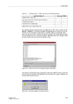
Page 621: ...6 B Basic Circle 6 57 Binary Inputs 10 3 Binary Inputs and Outputs 1 3 8 6 10 3 Binary Outputs 7 3 10 3 Binary Outputs for Switching Devices 5 23 Blocking 6 102 6 103 Blocking reclosure 6 154 Blocking Scheme 6 87 8 33 8 35 Breaker failure protection 6 211 Broken Conductor 6 219 Buffer Battery 6 216 C Calculation of the impedances Applying the Function Parameter Settings 6 38 Method of Operation 6 ...

Page 622: ...ng Operation 7 1 Messages 7 47 of Device Functions 7 22 of Switchgear 7 36 Voltages for Binary Inputs 8 10 Control of the internal automatic reclosure by an external protection device 6 163 Controlled Zone Z1B 6 53 6 63 Copying Setting Groups 6 14 Correction of measured values for Parallel Lines 6 37 on Parallel Lines 6 38 6 196 Correction of measured values for load current on double end fed line...

Page 623: ...tection in Earthed Systems 6 97 10 14 Protection Prerequisites 6 122 Recognition 6 30 Recognition during Single Pole Open Condition 6 32 Earth Fault Protection Teleprotection Schemes Applying the Function Parameter Settings 6 122 Method of Operation 6 114 Earth Impedance Residual Compensation 6 18 Compensation with Magnitude and Angle 6 19 Compensation with Scalar Factor 6 18 Earth Impedance Match...

Page 624: ...e 8 28 Independent Zones Z1 up to Z5 6 52 6 62 Indications 5 7 Indicators LEDs and Binary Outputs Output Relays 6 246 Information 5 10 Groups 5 10 on the Integrated Display LCD or to a Personal Computer 6 246 Retrieval 4 8 to a Control Centre 6 247 Initial Inspections 3 1 Initialize device 9 7 Inrush Stabilization 6 101 6 108 10 14 Inspection of Features and Ratings 3 3 Inspections upon Receipt 3 ...

Page 625: ...iming System 5 50 Panel with Four Line Display 4 5 Polygons 6 45 Serial Interface 4 6 Operating modes of the automatic reclosure circuit 6 154 Operating the auxiliary contacts of the circuit breaker 6 156 Operation interface 10 4 Using DIGSI 4 3 8 Using the Operator Control Panel 3 5 Operations 4 4 Operator Control Facilities 4 5 Control Panel 3 5 Control Panel On Device 4 5 Optical Communication ...

Page 626: ...of Information Fault Records 7 20 Messages 7 2 Switching Statistics 7 11 Read out of Measured Values 7 13 Read out on the Operator Control Panel 4 30 Real Time Clock and Buffer Battery 10 29 Rear Service Modem Interface 10 4 Reassembling the Device 9 11 Remote 4 8 4 14 Remote Trip of the Circuit Breaker at the Opposite Line End 6 130 Replacing the Buffer Battery 9 4 Replacing the Power Supply Fuse...

Page 627: ...ual closing 6 186 Synchronization and tripping check 1 9 Synchronization Offset 5 50 System SCADA Interface 7 4 8 19 10 5 System starpoint neutral 6 17 T Tagging 4 16 7 44 Technical Data 10 1 Teleprotection Methods 6 77 6 113 Supplement 1 7 with Distance Protection 8 32 with Earth Fault Protection 6 107 8 34 Terminal Blocks 2 18 Termination variants 8 6 Test of the Binary Inputs 8 38 of the Binary...

Page 628: ...ation 10 8 During Transport 10 8 View of Front Panel Housing Size 1 1 2 4 of Front Panel Housing Size 1 2 2 3 2 16 of Front Panel Housing Size1 1 2 17 of Rear Panel Housing Size 1 1 2 5 of Rear Panel Housing Size 1 2 2 5 Viewing Fault Records 7 20 Measured Values 3 6 3 10 Operational Messages 3 6 3 11 the Configuration on the Operating Panel 4 23 the Switching Statistics 7 11 Voltage Inputs 10 2 P...

Reviews: