Installation and Commissioning
8-21
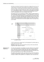
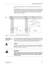
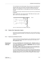
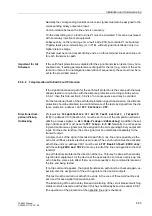
7SA522 Manual
C53000-G1176-C119-2
RS 485
Termination
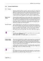
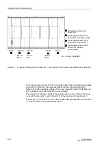
The RS485 interface is capable of half-duplex service with the signals A/A’ and B/B’
with a common relative potential C/C’ (DGND). Verify that only the last device on the
bus has the terminating resistors connected, and that the other devices on the bus do
not. The jumpers for the terminating resistors are on the interface module RS 485
(Figure 8-11) or on the Profibus module (Figure 8-12).
If the bus is extended, make sure again that only the last device on the bus has the
terminating resistors switched in, and that all other devices on the bus do not.
Time
Synchronization
Interface
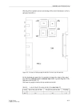
Either 5 VDC, 12 VDC or 24 VDC time synchronization signals can be processed if the
connections are made as indicated in Table
*) occupied, but must not be connected
Optical Fibres
Signals transmitted over optical fibres are unaffected by interference. The fibres guar-
antee electrical isolation between the connections. Transmit and receive connections
are identified with the symbols
for transmit and
for receive.
The character idle state for the optical fibre interface is “Light off.” If this setting is to
be changed, use the operating program DIGSI
®
4, as described in Section 5.5.
Table 8-9
Pin-assignments for the D-subminiature port of the
time synchronization
interface
Pin-No.
Designation
Signal meaning
1
P24_TSIG
Input 24 V
2
P5_TSIG
Input 5 V
3
M_TSIG
Return Line
4
M_TSYNC*)
Return Line*)
5
Screen
Shield potential
6
–
–
7
P12_TSIG
Input 12 V
8
P_TSYNC*)
Input 24 V*)
9
Screen
Shield potential
Summary of Contents for siprotec 7SA522
Page 20: ...7SA522 Manual C53000 G1176 C119 2 ...
Page 64: ...7SA522 Manual C53000 G1176 C119 2 ...
Page 89: ...SIPROTEC 4 Devices 4 25 7SA522 Manual C53000 G1176 C119 2 Figure 4 20 CFC Logic example ...
Page 408: ...7SA522 Manual C53000 G1176 C119 2 ...
Page 456: ...7SA522 Manual C53000 G1176 C119 2 ...
Page 516: ...7SA522 Manual C53000 G1176 C119 2 ...
Page 620: ...Appendix B 48 ...


