Installation and Commissioning
8-40
7SA522 Manual
C53000-G1176-C119-2
q
The response of the device must be checked in the
,VW
–column of the dialogue
box. To do this, the dialogue box must be updated. The options may be found below
under the margin heading “Updating the Display”.
If however the effect of a binary input must be checked without carrying out any switch-
ing in the plant, it is possible to trigger individual binary inputs with the hardware test
function. As soon as the first state change of any binary input is triggered and the
password nr. 6 has been entered,
all
binary inputs are separated from the plant and
can only be activated via the hardware test function.
q
Terminate the test sequence (see above under the margin heading „Ending the Pro-
cedure“).
Test of the LED’s
The LED’s may be tested in a similar manner to the other input/output components.
As soon as the first state change of any LED has been triggered,
all
LEDs are sepa-
rated from the internal device functionality and can only be controlled via the hardware
test frunction. This implies that no LED can be switched on anymore by e.g. a protec-
tion function or operation of the LED reset key.
Updating the
Display
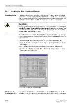
When the dialog box
+DUGZDUH7HVW
is opened, the present conditions of the hard-
ware components at that moment are read in and displayed. An update occurs:
−
for each harware component, if a command to change the condition is successfully
performed,
−
for all hardware components if the
8SGDWH
button is clicked,
−
for all hardware components with cyclical updating if the
$XWRPDWLF8SGDWH
VHF
field is marked.
Ending the
Procedure
To end the hardware test, click on
&ORVH
. The dialog box closes. The device becomes
unavailable for a brief start-up period immediately after this. Then all hardware com-
ponents are returned to the operating conditions determined by the plant settings.
8.3.8
Tests for the Circuit Breaker Failure Protection
If the device provides a breaker failure protection and if this is used, the integration of
this protection function in the system can be tested under practical conditions.
Due to the variety of application options and the available system configurations, it is
not possible to make a detailed description of the necessary tests. Local conditions,
system and protection plans must be observed.
Before starting the circuit breaker tests it is recommended to insulate at both ends the
feeder which is to be tested, i.e. line insulators and busbar insulators should be open
so that the breaker can be operated without risk.
Caution!
Also for tests on the local circuit breaker of the feeder a trip command to the
surrounding circuit breakers can be issued for the busbar. Therefore the tripping of the
surrounding circuit breakers (busbar) must be deactivated, e. g. by switching off the
corresponding control voltages.
Summary of Contents for siprotec 7SA522
Page 20: ...7SA522 Manual C53000 G1176 C119 2 ...
Page 64: ...7SA522 Manual C53000 G1176 C119 2 ...
Page 89: ...SIPROTEC 4 Devices 4 25 7SA522 Manual C53000 G1176 C119 2 Figure 4 20 CFC Logic example ...
Page 408: ...7SA522 Manual C53000 G1176 C119 2 ...
Page 456: ...7SA522 Manual C53000 G1176 C119 2 ...
Page 516: ...7SA522 Manual C53000 G1176 C119 2 ...
Page 620: ...Appendix B 48 ...


