Technical Data
10-14
7SA522 Manual
C53000-G1176-C119-2
10.5
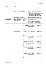
Earth Fault Protection in Earthed Systems
Characteristics
Definite time stages
(definite)
3I
0
>>>,3I
0
>>,3I
0
>
Inverse time stage
(IDMT)
3I
0P
one of the characteristics according to
Figure 10-1 to 10-7 can be selected
Earth Current
Stages
Very high set stage
3I
0
>>>
0.50 A to 25.00 A
1
)
(steps 0.01 A)
T
3I0>>>
0.00 s to 30.00 s
(steps 0.01 s)
or
∞
(ineffective)
High set stage
3I
0
>>
0.20 A to 25.00 A
1
)
(steps 0.01 A)
T
3I0>>
0.00 s to 30.00 s
(steps 0.01 s)
or
∞
(ineffective)
Overcurrent stage
3I
0
>
0.05 A to 25.00 A
1
)
(steps 0.01 A)
(definite time)
or
0.003 A to 25.000 A
2
)
(steps 0.001 A)
T
3I0>
0.00 s to 30.00 s
(steps 0.01 s)
or
∞
(ineffective)
Overcurrent stage
3I
0P
0.05 A to 25.00 A
1
)
(steps 0.01 A)
(inverse time acc. IEC)
or
0.003 A to 25.000 A
2
)
(steps 0.001 A)
T
3I0P
0.05 s to 3.00 s
(steps 0.01 s)
or
∞
(ineffective)
T
3I0Padd
0.00 s to 30.00 s
(steps 0.01 s)
Overcurrent stage
3I
0P
0.05 A to 25.00 A
1
)
(steps 0.01 A)
(inverse time acc. ANSI) or
0.003 A to 25.000 A
2
)
(steps 0.001 A)
D
3I0P
0.50 s to 15.00 s
(steps 0.01 s)
or
∞
(ineffective)
T
3I0Padd
0.00 s to 30.00 s
(steps 0.01 s)
Drop-out to pick-up ratios
approx. 0.95 for I
P
/I
N
≥
0.5
Tolerances
currents
3 % of set value or 1% of nominal current
with definite time
times
1 % of set value or 10 ms
Tolerances
currents
pick-up at 1.05
≤
I/3I
0P
≤
1.15
with inverse time (IEC)
times
5 % ± 15 ms
for 2
≤
I/3I
0P
≤
20
and T
3I0P
/s
≥
1
with inverse time (ANSI) times
5 % ± 15 ms
for 2
≤
I/3I
0P
≤
20
and D
3I0P
/s
≥
1
The set times are pure delay times with definite time protection.
1
) Secondary values based on I
N
= 1 A; for I
N
= 5 A they must be multiplied with 5.
2
) With highly sensitive earth current input, lower limit independent of I
N
,
secondary values based on I
N
= 1 A; for I
N
= 5 A they must be multiplied with 5.
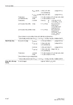
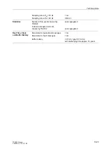
Inrush Stabilization
Second harmonic content for inrush
10 % to 45 %
(steps 1 %)
blocking
referred to fundamental wave
Inrush blocking is cancelled above
0.50 A to 25.00 A
1
)
(steps 0.01 A
1
)
Inrush stabilization may be switched effective or ineffective for each individual stage.
1
) Secondary values based on I
N
= 1 A; for I
N
= 5 A they must be multiplied with 5.
Summary of Contents for siprotec 7SA522
Page 20: ...7SA522 Manual C53000 G1176 C119 2 ...
Page 64: ...7SA522 Manual C53000 G1176 C119 2 ...
Page 89: ...SIPROTEC 4 Devices 4 25 7SA522 Manual C53000 G1176 C119 2 Figure 4 20 CFC Logic example ...
Page 408: ...7SA522 Manual C53000 G1176 C119 2 ...
Page 456: ...7SA522 Manual C53000 G1176 C119 2 ...
Page 516: ...7SA522 Manual C53000 G1176 C119 2 ...
Page 620: ...Appendix B 48 ...


