Configuration
5-4
7SA6 Manual
C53000-G1176-C156-2
Different pickup modes can be selected for the Distance Protection. The characteris-
tics of these modes are described in detail in Subsection 6.2.2. If the fault current mag-
nitude is a reliable criterion for the distinction between fault closure and load operation
(including tolerable overloading), set address
114
Dis. PICKUP
=
I> (over-
curr.)
(overcurrent pickup, Subsubsection 6.2.2.1). If the voltage drop is also re-
quired as pickup criterion, select
U/I
(voltage-controlled overcurrent pickup, Subsub-
section 6.2.2.2). For HV and EHV lines address setting
U/I/<phi>
(voltage & phase-
angle dependent current pickup, see Subsubsection 6.2.2.3) may be needed. For the
impedance starting the larges-set R-Zones and X-Zones of the distance zones form
the pickup criteria. If the
114
Dis. PICKUP =
Disabled
is set, the Distance Pro-
tection function and all functions related to it are not available.
Please take into consideration that the power swing supplement (refer also to Section
6.3) can only operate in conjunction with the impedance starting. Otherwise the sup-
plement is disabled, even if address
120
Power Swing
is set to
Enabled.
If the Distance Protection is to be supplemented with a teleprotection system, the de-
sired scheme can be selected in address
121
Teleprot. Dist.
. The following
schemes are available: the permissive underreach transfer scheme via pickup
PUTT
(Pickup)
and via the permissive overreach transfer scheme
POTT
, the signal com-
parison scheme
signal comparison
, the
Dir.Comp.Pickup
scheme, the
UNBLOCKING
scheme, the
BLOCKING
scheme as well as the schemes via Pilot wire
comparison (
Pilot wire comp
) and reverse interlocking
Rev. Interlock.
If
the device features a protection data interface for communicating via digital transmis-
sion ways, choose setting
POTT over Protection Interface
.
These schemes
are described in detail in Subsection 6.6.1. If the teleprotection supplement is not re-
quired for the distance protection, the setting must be
Disabled
.
The tripping characteristic group of the time delayed overcurrent protection can be set
in address
126
Backup overcurrent (Back-Up O/C)
. In addition to the definite
time overcurrent protection (DT), an inverse time overcurrent protection can be con-
figured in two different ways (depending on the order variant): either corresponding to
the IEC characteristics (
TOC IEC
), or to the ANSI characteristics (
TOC ANSI
). The
various characteristics are shown in the technical data. The time delayed overcurrent
protection may naturally also be disabled (
Disabled
).
If you are using the earth fault protection, you can complement it by teleprotection
schemes. Under address
132
Teleprot. E/F
you can select the desired mode. You
can choose between
Directional Comparison Pickup
, the
Unblocking
and
the
Blocking
mode. For a detailed description of these modes please read Sub-
section 6.8.1. If the device features a protection data interface for communication via
digital link, you must set
PUTT over Protection Interface
. If you do not want
to use teleprotection schemes with earth fault protection, set
Disabled
.
The tripping characteristic of the earth fault protection can also be selected, in this
case in address
131
Earth fault overcurrent (Earth Fault O/C)
. In ad-
dition to the definite time overcurrent stage (DT), with up to three sub-stages, it is also
possible (depending on the order variant) to configure an inverse earth fault stage.
This inverse stage may either correspond to the IEC characteristic (
TOC IEC
) or to
the ANSI characteristic (
TOC ANSI
), or to an inverse logarithmic characteristic (
TOC
Logarithm.
). If an inverse tripping stage is not required, the stage that is usually re-
Note:
When having changed address
110
, first save the changes by clicking onto the
OK
button. Then open the dialogue box again, since other setting options depend on ad-
dress 110.
Summary of Contents for siprotec 7SA6
Page 2: ...Siemens Aktiengesellschaft Book No C53000 G1176 C156 2 ...
Page 18: ...xviii 7SA6 Manual C53000 G1176 C156 2 ...
Page 32: ...Introduction 1 14 7SA6 Manual C53000 G1176 C156 2 ...
Page 82: ...Hardware and Connections 2 50 7SA6 Manual C53000 G1176 C156 2 ...
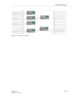
Page 119: ...SIPROTEC 4 Devices 4 25 7SA6 Manual C53000 G1176 C156 2 Figure 4 20 CFC Logic example ...
Page 190: ...Configuration 5 62 7SA6 Manual C53000 G1176 C156 2 ...
Page 652: ...Installation and Commissioning 8 78 7SA6 Manual C53000 G1176 C156 2 ...
Page 724: ...Technical Data 10 56 7SA6 Manual C53000 G1176 C156 ...
Page 800: ...Appendix A 76 7SA6 Manual C53000 G1176 C156 2 ...
Page 866: ...Appendix B 66 7SA6 Manual C53000 G1176 C156 2 ...


