Configuration
5-19
7SA6 Manual
C53000-G1176-C156-2
−
MVT
Measured Value with Time,
−
LV
Limit Value,
−
LVU
Limit Value, User Defined.
•
Metered Values:
−
MVMV
Metered Value of Measured Value,
−
PMV
Pulse Measured Value.
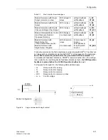
The information contains various properties depending on the information type, which
are partially fixed and may be partially influenced.
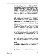
Source
The source denotes the origin of the information which the matrix receives for further
processing. Possible sources are:
−
BI
Binary Input,
−
F
Function key, which may serve to introduce a switching action,
−
C
CFC, i.e., message comes from user-definable logic,
−
S
Sytem Interface.
Destination
The destination indicates to which interface the information is forwarded. Possible
destinations are:
−
BO
Binary Output,
−
LED
LED display on the Device Front Panel,
−
O
Operation Event Buffer in the Device,
−
T
Trip Log Buffer in the Device,
−
S
System Interface,
−
C
CFC, Information is processed by CFC Program of the User-definable Logic.
−
CM
Control of switchgears if a switch plant is indicated in the Control Menu of
the device.
5.2.3
Establishing Information Properties
General
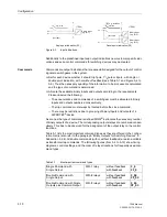
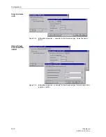
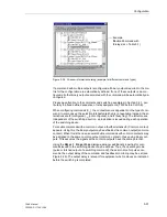
Different types of information contain different types of properties. To view the proper-
ties associated with a specific information unit (indication, command, etc.), position the
mouse on the specific row under
Information
, and then use the right mouse button
to access a context menu where
Properties
can be selected.
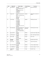
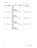
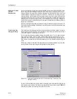
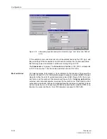
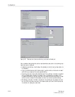
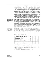
For example, if the cursor is positioned on a specific output indication, the right mouse
button is pressed, and the menu item
Properties
is selected, then a choice of
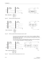
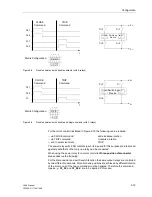
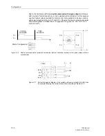
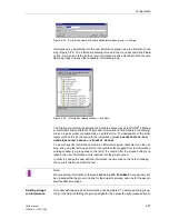
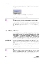
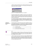
whether the indication should appear in the oscillographic fault records (Figures 5-14,
5-15, and 5-16) is presented. For internal single point indications, the default status of
the indication (on, off, or undefined) after device reset can be selected as well (Figure
5-15).
Note that the possible properties of information for the system interface depend on the
facilities of transmission protocol. See also Section “Protocol Dependent Functions” in
the Appendix.
Summary of Contents for siprotec 7SA6
Page 2: ...Siemens Aktiengesellschaft Book No C53000 G1176 C156 2 ...
Page 18: ...xviii 7SA6 Manual C53000 G1176 C156 2 ...
Page 32: ...Introduction 1 14 7SA6 Manual C53000 G1176 C156 2 ...
Page 82: ...Hardware and Connections 2 50 7SA6 Manual C53000 G1176 C156 2 ...
Page 119: ...SIPROTEC 4 Devices 4 25 7SA6 Manual C53000 G1176 C156 2 Figure 4 20 CFC Logic example ...
Page 190: ...Configuration 5 62 7SA6 Manual C53000 G1176 C156 2 ...
Page 652: ...Installation and Commissioning 8 78 7SA6 Manual C53000 G1176 C156 2 ...
Page 724: ...Technical Data 10 56 7SA6 Manual C53000 G1176 C156 ...
Page 800: ...Appendix A 76 7SA6 Manual C53000 G1176 C156 2 ...
Page 866: ...Appendix B 66 7SA6 Manual C53000 G1176 C156 2 ...

