Configuration
5-35
7SA6 Manual
C53000-G1176-C156-2
Configuring the
Metered Value
Window as a Desti-
nation
User defined pulse values and metered values derived from the measured values may
be configured into the metered value window so that they may be displayed at the front
relay panel. They are then available in the corresponding measured value window in
the display of the device.
Retrieving Device
Configurations
from the Device
Front
Retrieving the configurations is also possible from the device front. You may access
configuration information under
Main Menu
:
→
Settings
→
Masking (I/O)
.
The menu title
MASKING (I/O)
appears in the title bar. Configuration information re-
garding each (physical) input and output is indicated in the display.
Any new user defined information is also shown in the display once loaded into the
relay from DIGSI
®
4.
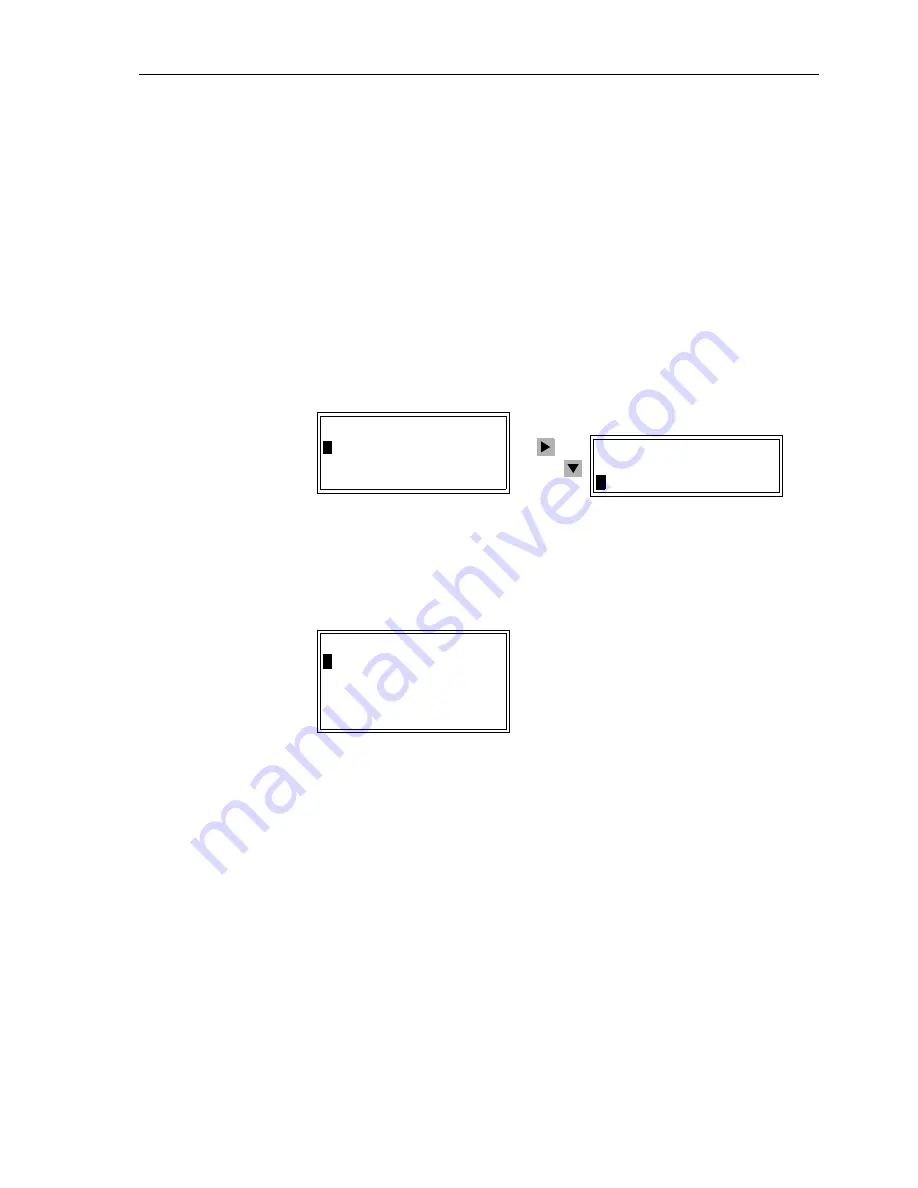
When selecting the
MASKING (I/O)
menu, either binary inputs, LEDs, or binary out-
puts may be selected. Selection of binary inputs is illustrated in Figure 5-30.
Figure 5-30
Reading the configuration in the front display of the device — example
Information regarding a binary input may be displayed by using the navigation keys to
select the binary input. See Figure 5-31.
Figure 5-31
Selection of binary input 2 — example
In the example of Figure 5-31, information is displayed regarding binary input 2. The
display for binary input 2 indicates that it is configured as reset of the latched LEDs
using a single point indication with voltage active (High). The present conditions of bi-
nary input 2 is also given as 0 (not active). If a binary input is active, a 1 is displayed.
Assignment of LEDs may be indicated at the relay, itself, using a replaceable labelling
strip with plain text on the front panel located, directly next to the LEDs.
The LED indication presettings which are present in the device when it leaves the
factory, those of the binary inputs and the output relay pre-configuration are
summarised in Appendix A.4.
MASKING (I/O) 01/03
---------------------
>Binary Inputs –> 1
>
LED –> 2
Binary Outputs –> 3
BINARY INPUTS 02/11
---------------------
>Binary Input 1–> –
BINARY INPUT
2
---------------------
>>Reset LED SP H
---------------------
Summary of Contents for siprotec 7SA6
Page 2: ...Siemens Aktiengesellschaft Book No C53000 G1176 C156 2 ...
Page 18: ...xviii 7SA6 Manual C53000 G1176 C156 2 ...
Page 32: ...Introduction 1 14 7SA6 Manual C53000 G1176 C156 2 ...
Page 82: ...Hardware and Connections 2 50 7SA6 Manual C53000 G1176 C156 2 ...
Page 119: ...SIPROTEC 4 Devices 4 25 7SA6 Manual C53000 G1176 C156 2 Figure 4 20 CFC Logic example ...
Page 190: ...Configuration 5 62 7SA6 Manual C53000 G1176 C156 2 ...
Page 652: ...Installation and Commissioning 8 78 7SA6 Manual C53000 G1176 C156 2 ...
Page 724: ...Technical Data 10 56 7SA6 Manual C53000 G1176 C156 ...
Page 800: ...Appendix A 76 7SA6 Manual C53000 G1176 C156 2 ...
Page 866: ...Appendix B 66 7SA6 Manual C53000 G1176 C156 2 ...


