Configuration
5-52
7SA6 Manual
C53000-G1176-C156-2
5.5
Draft of a Feeder Control Display
General
Information
The feeder control display is used to visualize the switch positions and to control the
switching objects. That is why only the objects relevant for the switching process are
usually displayed while measured values and such have been omitted. The feeder
control display must be selected.
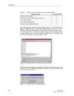
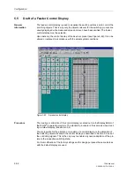
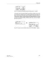
Upon delivery, the control display of the device is preset (see Figure 5-49). It can be
altered or replaced in accordance with the actual system conditions.
Figure 5-49
A preset control display
Procedure
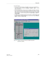
The creation or alteration of the control display is carried out via the Display Editor of
the DIGSI
®
4 operating program. The standard procedure is the same as when creat-
ing a default display (see section 5.4).
The prerequisite for the alteration or creation of a control display is the allocation of
the switching objects located in the control display as described in Section 5.2 and of
the controlling signals. This is the only way to enable a dynamic adaptation of the pic-
ture to the respective switching state.
For the modification of the factory settings and for design purposes the same tools as
with the default display are used.
Summary of Contents for siprotec 7SA6
Page 2: ...Siemens Aktiengesellschaft Book No C53000 G1176 C156 2 ...
Page 18: ...xviii 7SA6 Manual C53000 G1176 C156 2 ...
Page 32: ...Introduction 1 14 7SA6 Manual C53000 G1176 C156 2 ...
Page 82: ...Hardware and Connections 2 50 7SA6 Manual C53000 G1176 C156 2 ...
Page 119: ...SIPROTEC 4 Devices 4 25 7SA6 Manual C53000 G1176 C156 2 Figure 4 20 CFC Logic example ...
Page 190: ...Configuration 5 62 7SA6 Manual C53000 G1176 C156 2 ...
Page 652: ...Installation and Commissioning 8 78 7SA6 Manual C53000 G1176 C156 2 ...
Page 724: ...Technical Data 10 56 7SA6 Manual C53000 G1176 C156 ...
Page 800: ...Appendix A 76 7SA6 Manual C53000 G1176 C156 2 ...
Page 866: ...Appendix B 66 7SA6 Manual C53000 G1176 C156 2 ...

