Configuration
5-57
7SA6 Manual
C53000-G1176-C156-2
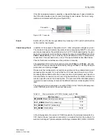
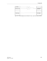
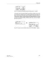
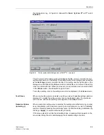
Figure 5-54
Reading and setting the front interface at the device panel — example
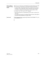
The type and number of system interface(s) is dependent on the device type and ver-
sion and might be completely missing. The system interface data may be read at the
device, but cannot be modified there, whereas the data for the operator and service
interface can be modified. In addition to the settings already mentioned for the opera-
tor and service interfaces, the signal idle state for an optical link may also be read at
the device. For an electrical interface, the response “
OFF–Sig. Inactive
” appears
as shown in Figure 5-55.
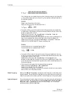
Figure 5-55
Read-out of system interface setting values in the device display — example
FRONT PORT 01/04
---------------------
>Phys.Addr. >>>>>1
>
Baudrate 38400 Baud
Parity 8E1 (DIGSI)
SYSTEM PORT
---------------------
>IEC60870–5–103 –> 1
IEC60870–5–103
--------------------
>Phys.Address > 1
>
Baudrate 38400 Baud
Parity 8E1 (DIGSI)
Gaps 0.0sec
Summary of Contents for siprotec 7SA6
Page 2: ...Siemens Aktiengesellschaft Book No C53000 G1176 C156 2 ...
Page 18: ...xviii 7SA6 Manual C53000 G1176 C156 2 ...
Page 32: ...Introduction 1 14 7SA6 Manual C53000 G1176 C156 2 ...
Page 82: ...Hardware and Connections 2 50 7SA6 Manual C53000 G1176 C156 2 ...
Page 119: ...SIPROTEC 4 Devices 4 25 7SA6 Manual C53000 G1176 C156 2 Figure 4 20 CFC Logic example ...
Page 190: ...Configuration 5 62 7SA6 Manual C53000 G1176 C156 2 ...
Page 652: ...Installation and Commissioning 8 78 7SA6 Manual C53000 G1176 C156 2 ...
Page 724: ...Technical Data 10 56 7SA6 Manual C53000 G1176 C156 ...
Page 800: ...Appendix A 76 7SA6 Manual C53000 G1176 C156 2 ...
Page 866: ...Appendix B 66 7SA6 Manual C53000 G1176 C156 2 ...

