Functions
6-96
7SA6 Manual
C53000-G1176-C156-2
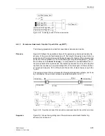
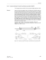
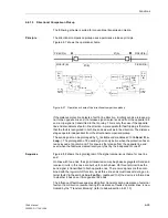
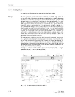
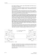
Figure 6-54
Operation scheme of the direct underreach transfer trip method
6.6.1.4
Permissive Overreach Transfer Trip (POTT)
The following procedure is suited for both conventional and digital transmission media.
Principle
The permissive overreach transfer mode uses a permissive release principle. The
overreaching zone Z1B set beyond the opposite station is decisive. This mode can
also be used on extremely short lines where a setting of 85 % of line length for zone
Z1 is not possible and accordingly selective non-delayed tripping could not be
achieved. In this case however zone Z1 must be delayed by T1, to avoid non selective
tripping by zone Z1.
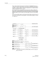
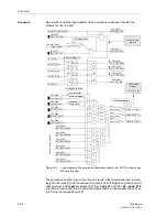
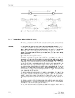
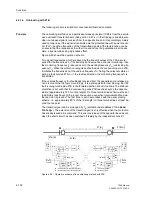
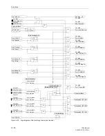
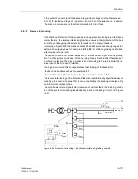
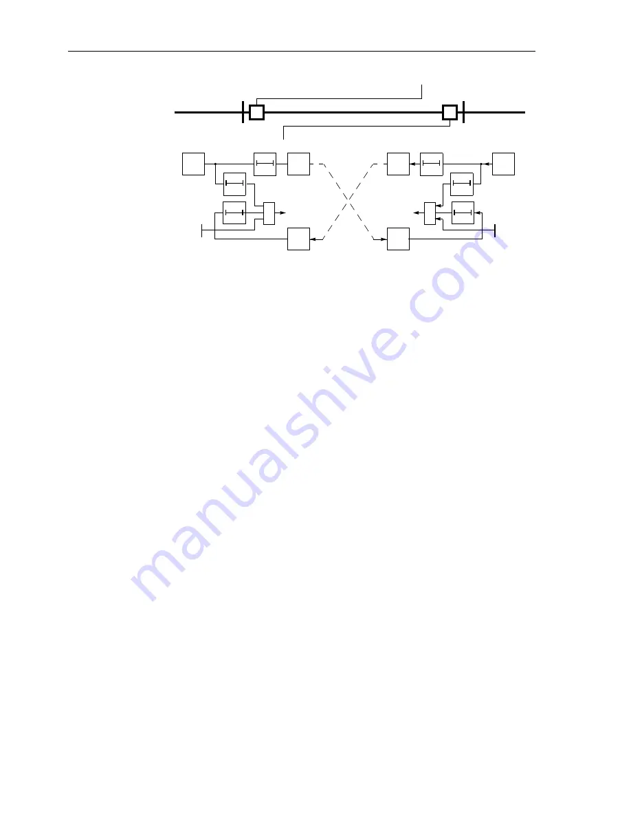
Figure 6-55 shows the operation scheme.
If the distance protection recognizes a fault inside the overreaching zone Z1B, it ini-
tially sends a release signal to the opposite line end. If a release signal from the op-
posite line end is received, a trip signal is initiated via the tripping relay. A prerequisite
for fast tripping is therefore that the fault is recognized inside Z1B in the forward direc-
tion at both line ends. The distance protection is set such that the overreaching zone
Z1B reaches beyond the opposite station (approximately 120% of line length). On
three terminal lines, Z1B must be set to reliably reach beyond the longer line section
even with intermediate infeed via the tee point. The first zone is set in accordance with
the normal time grading, i.e. approximately 85 % of the line length, on three terminal
lines, at least beyond the tee point.
The transmit signal can be prolonged by T
S
(settable under address
2103
Send Pro-
long.
). This extension of the transmit signal is only active when the protection has
already issued a trip command. This ensures the release of the opposite line end,
even when the short-circuit has been locally cleared very fast by the independent zone
Z1.
For all zones, except for Z1B, the tripping takes place without a release signal from
the opposite line end. This allows the protection to operate with the normal grading
characteristic independent of the signal transmission.
For this procedure, transmission via a protection data interface (if provided) is offered.
T
v
T
v
A
B
Z1(A)
Z1
(A)
T
S
T1
≥
1
Trip
Trans.
Rec.
further
Zones
Z1(B)
Z1
(B)
T
S
T1
≥
1
Trip
Trans.
Rec.
further
Zones
Summary of Contents for siprotec 7SA6
Page 2: ...Siemens Aktiengesellschaft Book No C53000 G1176 C156 2 ...
Page 18: ...xviii 7SA6 Manual C53000 G1176 C156 2 ...
Page 32: ...Introduction 1 14 7SA6 Manual C53000 G1176 C156 2 ...
Page 82: ...Hardware and Connections 2 50 7SA6 Manual C53000 G1176 C156 2 ...
Page 119: ...SIPROTEC 4 Devices 4 25 7SA6 Manual C53000 G1176 C156 2 Figure 4 20 CFC Logic example ...
Page 190: ...Configuration 5 62 7SA6 Manual C53000 G1176 C156 2 ...
Page 652: ...Installation and Commissioning 8 78 7SA6 Manual C53000 G1176 C156 2 ...
Page 724: ...Technical Data 10 56 7SA6 Manual C53000 G1176 C156 ...
Page 800: ...Appendix A 76 7SA6 Manual C53000 G1176 C156 2 ...
Page 866: ...Appendix B 66 7SA6 Manual C53000 G1176 C156 2 ...


